DS8100
14
2
Aux. Interface/Input Signal Connector B
A1
A2
1
15
scanner side
external view
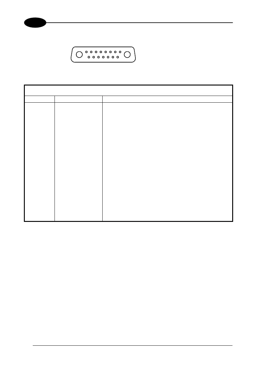
Figure 11 - Aux. Interface/Input Signal connector B (female)
Aux. Interface/Input Signal Connector B pinout
Pin Name Function
A1 GND ground
A2 VS power supply
1 GND485 RS485 ground reference
2 I.U. (
TXDEBUG
) only for service use
3 I.U. (
GNDDEBUG
) only for service use
4 I.U. (
RXDEBUG
) only for service use
5 GNDAUX232 auxiliary RS232 ground
6 RXAUX232 auxiliary RS232 input
7 TXAUX232 auxiliary RS232 output
8 RXTX485+ positive RS485 transmit/receive
9 RXTX485- negative RS485 transmit/receive
10 ENC+/PS3+ encoder/presence sensor 3 signal (positive pin)
11 ENC-/PS3- encoder/presence sensor 3 signal (negative pin)
12 PS2+ presence sensor 2 signal (positive pin)
13 PS2- presence sensor 2 signal (negative pin)
14 PS1+ presence sensor 1 signal (positive pin)
15 PS1- presence sensor 1 signal (negative pin)
 Loading...