DS8100
22
2
DS8100
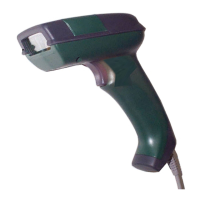
MAX. 300 METERS
8
C.L. IN-
7
C.L. IN+
3
C.L. OUT-
2
C.L. OUT+
USER INTERFACE
+
+
Figure 19 - 20 mA C.L. passive connections
2.4.4 Auxiliary Interface
The auxiliary serial interface of the DS8100 Serial Interface version is equipped with
both RS232 and RS485 half-duplex interface connections.
The signals for the auxiliary interface are available on the Aux. Interface A and B
connectors to simplify the master/slave connections (Figure A, 13 and 14).
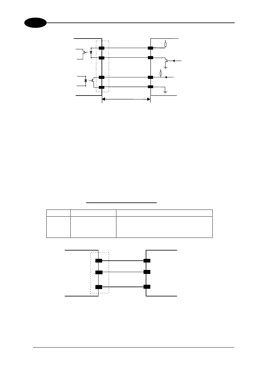
RS232 Auxiliary Interface
The following pins of the Aux. Interface B connector connector are used:
Pin Name Function
5 GNDAUX232 ground
6 RXAUX232 receive data
7 TXAUX232 transmit data
TXD
RXAUX232
RXD
TXAUX232
7
5
GNDAUX232
GND
DS8100
USER INTERFACE
6
Figure 20 - RS232 Auxiliary interface connections
When the auxiliary interface is permanently connected as part of the system cabling,
it is recommended to connect the cable shield to earth ground.
 Loading...