INSTALLATION – DS8100 SERIAL INTERFACE
17
2
RS232 Interface
The main serial interface is used in this case for point-to-point connections; it handles
communication with the Host computer and allows both transmission of code data
and configuring the scanner.
The following pins of the Main Interface connector (Figure A, 15) are used for RS232
interface connection:
Pin Name Function
2 TXD transmitted data
3 RXD received data
5 GND ground
7 CTS clear to send
8 RTS request to send
It is always advisable to use shielded cables. The overall maximum cable length
must be less than 15 m (49.2 ft).
DS8100 USER INTERFACE
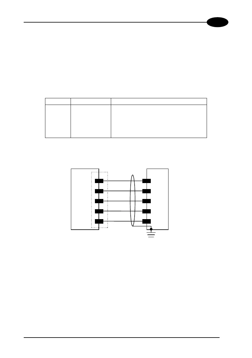
TXD
RXD
CTS
RTS
GND
RXD
TXD
GND
2
3
7
8
5
Earth
Ground
Figure 14 - RS232 connections
The RTS and CTS signals control data transmission and synchronize the connected
devices.
If the RTS/CTS hardware protocol is enabled, the DS8100 activates the RTS output
to indicate a message can be transmitted. The receiving unit must activate the CTS
input to enable the transmission.
 Loading...