3. By selecting the “PackTrack Calibration” option a further dialog box appears allowing to
start calibration:
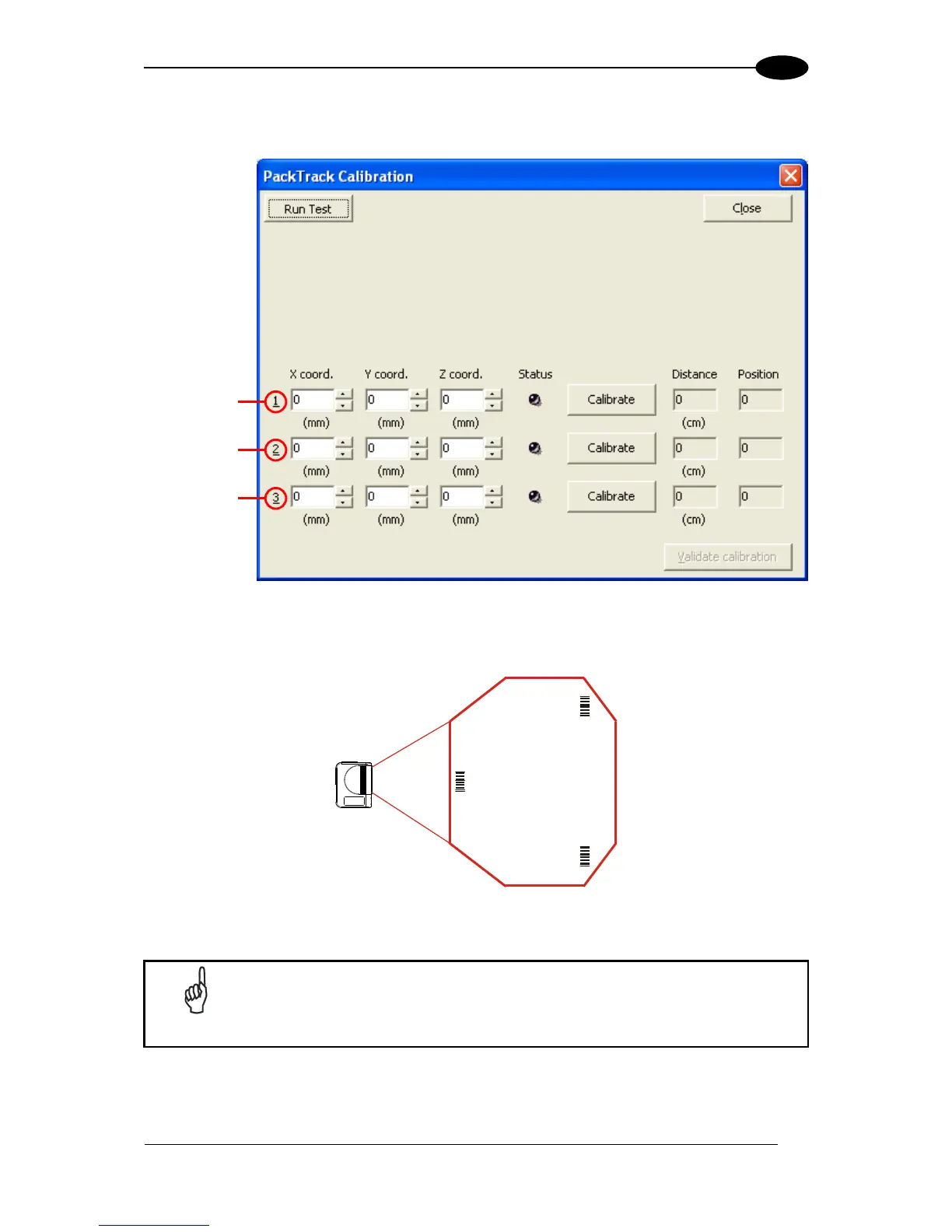
Figure 100 – Performing the PackTrack™ Calibration
4. Place the code at one of the desired positions on the scan line (i.e. Position 1).
5. Measure the X, Y and Z coordinates relative to the center of the code and enter them
into the corresponding edit boxes.
In the vast majority of systems the x and z data are not necessary. For
these cases set x = 0, z= 0 during the calibration procedure.