EasyManuals Logo

Datalogic DS8100A User Manual

Datalogic DS8100A
141 pages
To Next Page IconTo Next Page
To Previous Page IconTo Previous Page
Page #42 background imageLoading...
Page #42 background image
DS8100A REFERENCE MANUAL
28
3
The driving logic of the input signals may be powered, for convenience, with the voltage
supply at the CBX terminal block spring clamps (V+) and (V-). In this case, however, the
device is no longer electrically isolated. The voltage available on pins V+ and V-, is physically
the same as the input power for the scanner (Vdc and GND).
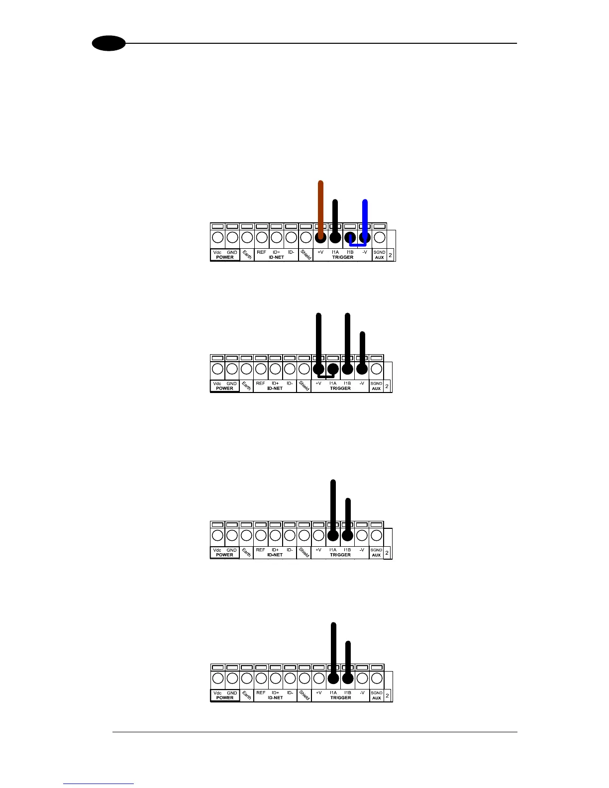
INPUT 1 (EXTERNAL TRIGGER/PS) CONNECTIONS USING DS8100A POWER
(brown)
(black) (blue)
MEP-593 PH-1 Photocell (PNP)
Figure 24 MEP-593 PH-1 (PNP) External Trigger/PS Using DS8100A Power
Power to Input
Photocell Signal
Photocell
Reference
NPN Photocell
Figure 25 - NPN External Trigger/PS Using DS8100A Power
INPUT 1 (EXTERNAL TRIGGER/PS) CONNECTIONS USING EXTERNAL POWER
External Device
Ground Reference
Input
Signal
Figure 26 - PNP External Trigger/PS Using External Power (i.e. PLC signal)
External Device
Power Reference
Input
Signal
Figure 27 - NPN External Trigger/PS Using External Power (i.e. PLC signal)

Table of Contents

Questions and Answers:

Question and Answer IconNeed help?

Do you have a question about the Datalogic DS8100A and is the answer not in the manual?

Datalogic DS8100A Specifications

General IconGeneral
BrandDatalogic
ModelDS8100A
CategoryBarcode Reader
LanguageEnglish

Related product manuals