vPad-A1 OPERATORS MANUAL
4.7 Non-Invasive Blood Pressure (NIBP)
4.7.1 General
In oscillometric
Non-Invasive Blood Pressure (NIBP) monitoring systems, a patient’s blood pressure is
assessed by inflating a cuff around the patient’s arm. The cuff contains an air bladder that serves two
purposes: one, to compress the arm such that blood flow can be restricted by various degrees; and,
secondly, to convert changes in the arm’s volume into small variations in air pressure within the cuff. Once
a blood pressure measurement is complete, the cuff is deflated.
The pressure variations detected by the monitor are known as oscillometric signals. As shown in human
experiments and repeatedly in clinical trials, the sizes of these oscillometric pulses can be mapped to certain
clinically significant physiological parameters such as Systolic Blood Pressure (SYS), Mean Arterial
Pressure
(MAP), and Diastolic Blood Pressure (DIA). In general, the sizes of oscillometric pulses increase
as the cuff is inflated from zero pressure, continue increasing past the DIA, and peaks when the cuff’s
internal pressure is close to the patient’s MAP. When pressure exceeds MAP, pulse sizes will gradually
decrease as cuff pressure rises past SYS, then further until the cuff fully restricts patient blood flow to the
distal portions of the arm.
This relationship between cuff pressure, blood pressure, and the size of oscillometric pulses is known as an
Envelope. As more NIBP monitors meet regulatory approval through clinical trials, they show that there is
not one universal, ideal Envelope as was proposed early in the history of the oscillometric NIBP technique,
but rather a “best fit” relationship that is dependant on the selected trial population.
To fully test a monitor that measures NIBP, the A1 provides multiple test features that can be accessed by
touching the NIBP tab on the left side of the vPad-A1 Main screen (
Figure 17
).
4.7.2 NIBP Simulation
NIBP Simulation on the A1 injects small pulsatile pressure waves into a test
pneumatic system that includes the NIBP monitor, its air hose(es), a blood pressure
cuff, and the simulator. The cuff should be wrapped around a test cylinder or
mandrel that is large enough to make a snug (not tight) fit. Hose adapters allow the
simulator to be connected between the distal end of the hose(es) and the cuff, such
that the injected pulses would appear to the monitor as oscillometric signals.
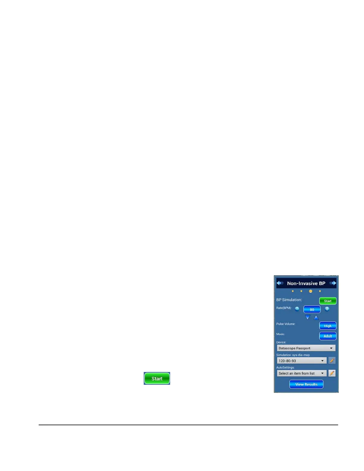
On the
NIBP Simulation page in
Figure 76
, shown by default when first entering
the NIBP tab, users can adjust the simulation parameters that will become active
when the feature is launched with the button.
Figure 76
Manual Operation/Chapter 4 # Page 55
 Loading...