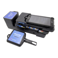
vPad-A1 OPERATORS MANUAL
4.8.2.3 Calibration: SpO2 R-Curves
In a typical pulse oximeter, the SpO2 R-Curve is the means by which that
particular device translates its measurement of light transmission through
oxygenated blood to an oxygen saturation in percent. Individual R-Curves
are derived through clinical studies and, while similar, may be different for
each make and model encountered. vPad-A1 has R-Curves pre-
programmed for a number of common monitor makes and models;
however, users may need to add a new device to the make/model menus.
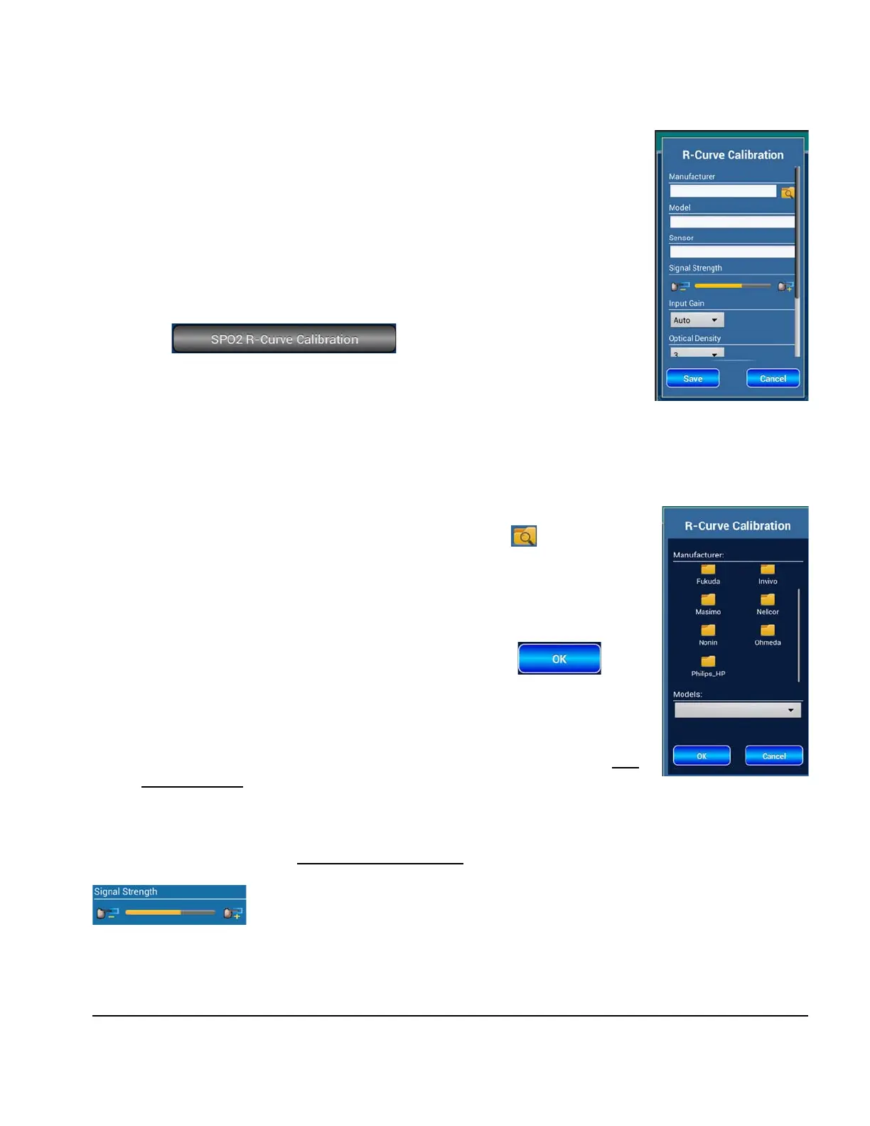
The button in the Settings panel launches
a calibration tool for SpO2 R-Curves. The Manufacturer, Model, and the
(optional) Sensor field in the calibration tool uniquely identify each
individual R-Curve.
Note
: The Sensor identifier accounts for small variations in output that can exist
between an OEM sensor (e.g. Nellcor's DS100) and a third-party
replacement sensor (e.g. EnviteC).
Users can enter new information into the three text input boxes as
appropriate for the new device. Alternatively, press the Folder Search
icon to choose an existing R-Curve as template. A new window will show a
folder list of known Manufacturers, as in
Figure 97
.
Touching any Manufacturer folder will populate the Models dropdown menu
with existing devices in the same category. Once the desired Model is chosen
from the list, users can confirm the selection by pressing .
If a template R-Curve was successfully selected, the Manufacturer, Model, and
(optional) Sensor fields will now be populated with text from the template,
along with all additional data fields discussed below. Users should edit the
auto-filled text to create a new device
R-Curve; otherwise, the template may
be over-written with the newly-entered data.
Having identified the oximeter device, the following steps will create for it a suitable R-Curve.
Optimize Signal Strength
• When the pulse oximeter sensor is placed on the vPad-O2 finger, the
Signal Strength indicator will display the output of the oximeter's
sensor in real time.
Figure 96
Figure 97
Figure 98
Manual Operation/Chapter 4 # Page 67
 Loading...