Antenna Delay for details of calibration of antenna delay. The units here are the same as those used for
system time and time stamps, i.e. 499.2 MHz × 128, so the least significant bit is about 15.65 picoseconds.
NB: This register is not preserved during SLEEP or DEEPSLEEP and so needs reprogramming after a
wakeup event in order to obtain the correct adjustment of the TX_STAMP.
The TX_ANTD is corrupted during wake-up (assuming the ONW_LDC bit in Sub-Register 0x2C:00 –
AON_WCFG is set to restore configurations) the high-octet of the receive antenna delay as
configured in Sub-Register 0x2E:1804 – LDE_RXANTD overwrites the low-octet of TX_ANTD.
7.2.27 Register file: 0x19 – Reserved
Register map register file 0x19 is reserved.
7.2.28 Register file: 0x1A – Acknowledgement time and response time
Acknowledgement Time and Response Time
Register map register file 0x1A is a configuration register used for specifying turn-around times for DW1000
to use when automatically switching between TX mode and RX modes. The ACK_RESP_T register contains
the following bitmapped sub-fields:
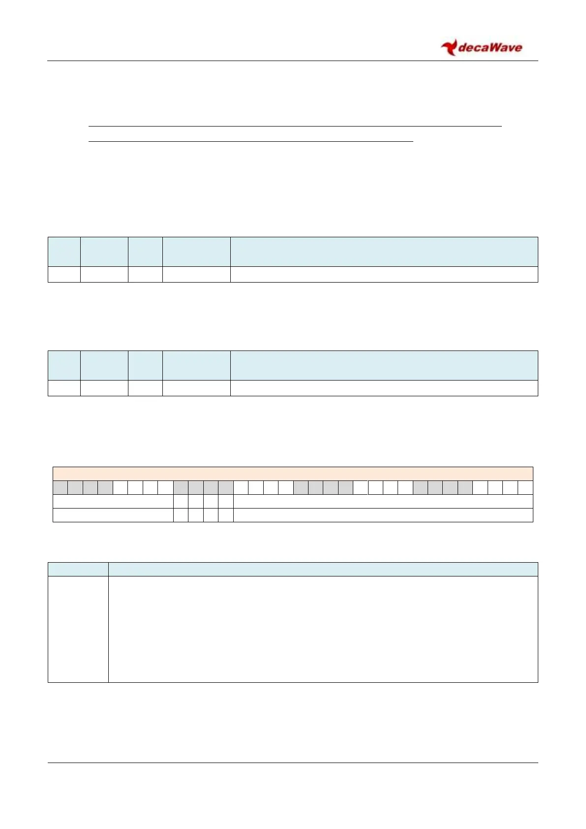
REG:1A:00 – ACK_RESP – RX Frame Information
The individual sub-fields are described below:
Description of fields within Register file: 0x1A – Acknowledgement time and response time
W4R_TIM
reg:1A:00
bits:19–0
Wait-for-Response turn-around Time. This 20-bit field is used to configure the turn-around
time between TX complete and RX enable when the wait for response function is being used.
This function is enabled by the WAIT4RESP control in Register file: 0x0D – System Control
Register. The time specified by this W4R_TIM parameter is in units of approximately 1 µs, or
128 system clock cycles. This configuration may be used to save power by delaying the turn-on
of the receiver, to align with the response time of the remote system, rather than turning on
the receiver immediately after transmission completes. For more details see section 5.4 –
Transmit and automatically wait for response.