EasyManua.ls Logo

DEEP SEA ELECTRONICS DSEGenset DSE3110 - TYPICAL WIRING DIAGRAM

DEEP SEA ELECTRONICS DSEGenset DSE3110
56 pages
Print Icon
To Next Page IconTo Next Page
To Previous Page IconTo Previous Page
Loading...
Installation
Page 25 of 56
057-086 ISSUE: 6
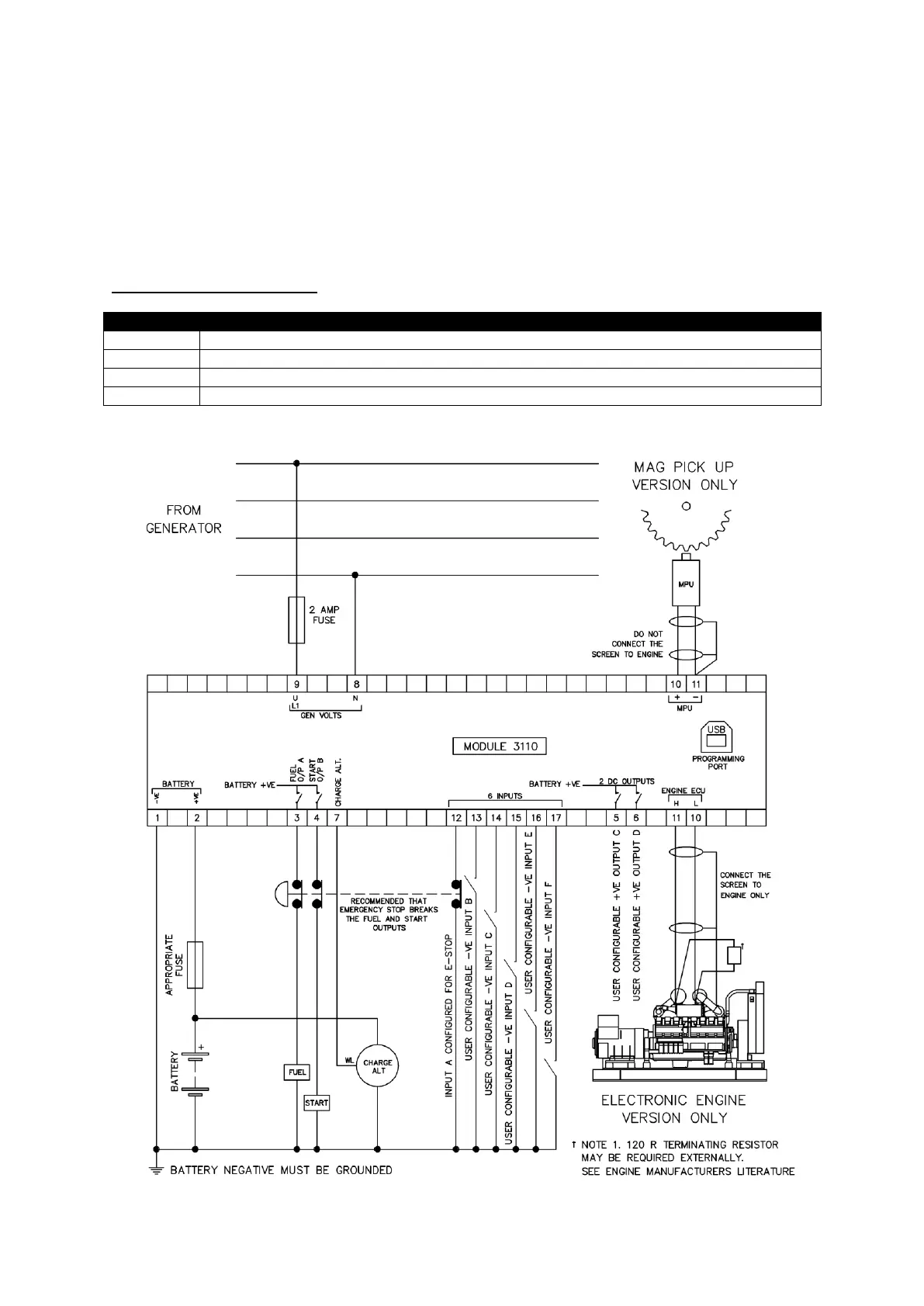
3.3 TYPICAL WIRING DIAGRAM
As every system has different requirements, these diagrams show only a typical system and do not
intend to show a complete system.
Genset manufacturers and panel builders may use these diagrams as a starting point; however, refer
to the completed system diagram provided by the system manufacturer for complete wiring detail.
Further wiring suggestions are available in the following DSE publications, available at
www.deepseaelectronics.com
DSE Part
Description
056-022
Switchgear Control
056-091
Equipotential Earth Bonding
056-092
Best Practices for Wiring Resistive Sensors
057-004
Electronic Engines and DSE Wiring

Table of Contents

Related product manuals