2.4 TERMINAL SPECIFICATION
NOTE: For purchasing additional connector plugs from DSE, see the section entitled
Maintenance, Spares, Repair and Servicing elsewhere in this document.
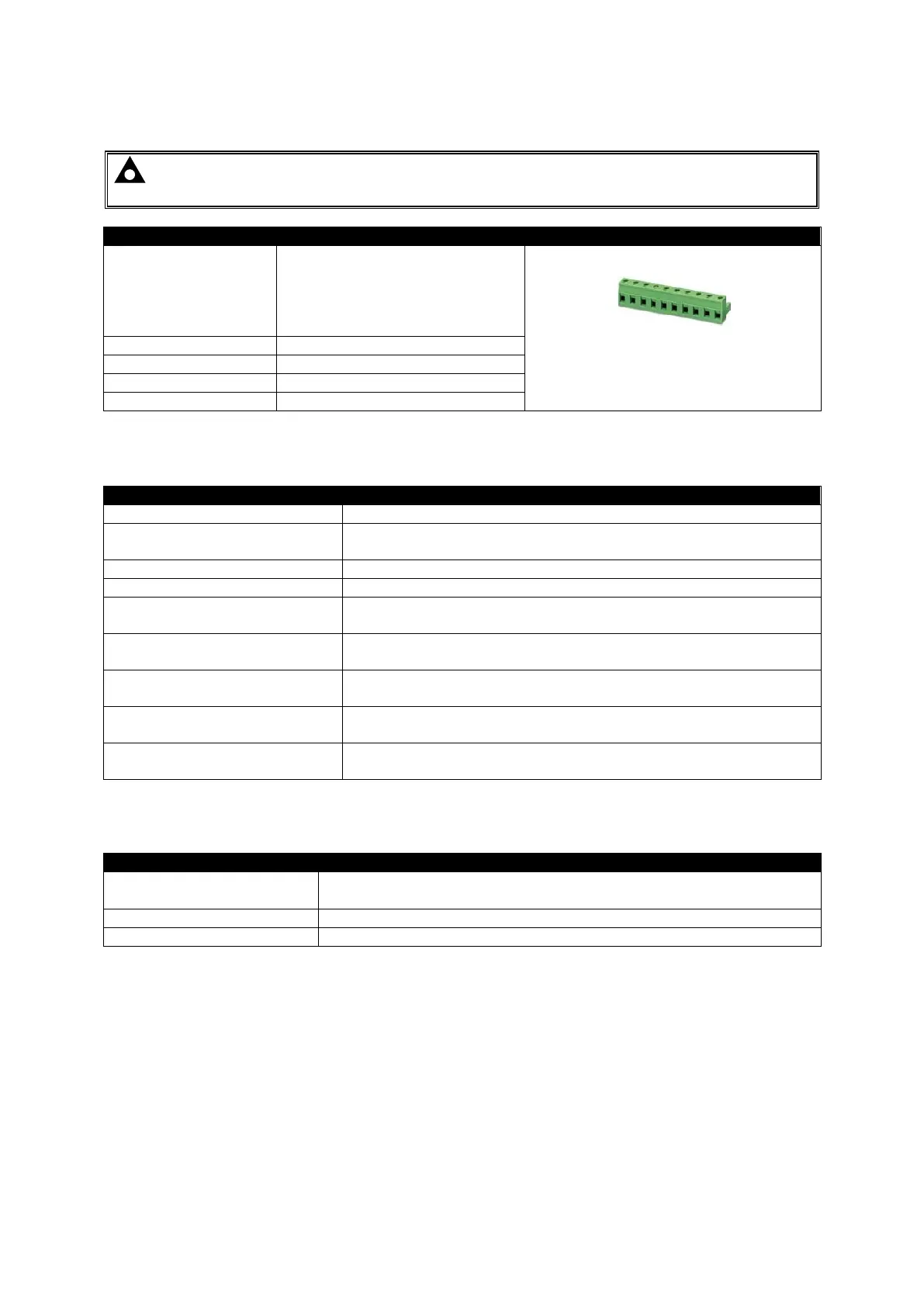
Two part connector.
Male part fitted to module
Female part supplied in module
packing case - Screw terminal,
rising clamp, no internal spring.
Example showing cable entry and screw
terminals of a 10 way connector
2.5 POWER SUPPLY REQUIREMENTS
Able to survive 0 V for 50 ms providing the supply was at least
10 V before the dropout and recovers to 5 V afterwards.
35 V continuous (60 V protection)
Reverse Polarity Protection
Maximum Operating Current
3110-001-xx to 3110-005-xx
35 mA at 12 V
33 mA at 24 V
Maximum Operating Current
3110-006-xx onwards
76 mA at 12 V
61 mA at 24 V
Nominal Standby Current
3110-001-xx to 3110-005-xx
23 mA at 12 V
18 mA at 24 V
Nominal Standby Current
3110-006-xx onwards
45 mA at 12 V
43 mA at 24 V
Maximum Current When In
Sleep Mode
3.5 mA at 12 V
3.5 mA at 24 V
2.5.1 MODULE SUPPLY INSTRUMENTATION DISPLAY
0 V to 70 V DC
Maximum continuous operating voltage of 35 V DC
 Loading...