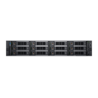
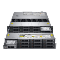
Figure 120. Cable routing – 24 x 2.5 inch drive backplane with 4 x 3.5 (with 4 x 2.5 adapter) mid drive tray and 4 x 2.5 rear drive cage
1 backplane 2 backplane signal cable
3 backplane power cable 4 4 x 3.5 inch drives (with 4 x 2.5 adapter)
5 SAS cable 6 SAS cable
7 SAS cable 8 rear 4 x 2.5 inch drive backplane
9 adapter PERC on slot 3 10 mid drive backplane
158 Installing and removing system components
 Loading...

