3. If you are replacing the system board, remove all the components that are listed in the Remove the system board section.
NOTE: The procedure to install the system board is same for Rear Accessed and Front Accessed configurations.
Steps
1. Unpack the new system board assembly.
NOTE: Do not remove the processor socket cover until the system board is assembled in the chassis and the processor
and heat sink module is ready for installation.
CAUTION: Do not lift the system board by holding a memory module, processor, or other components.
CAUTION: Take care not to damage the system identification button while placing the system board into the
chassis.
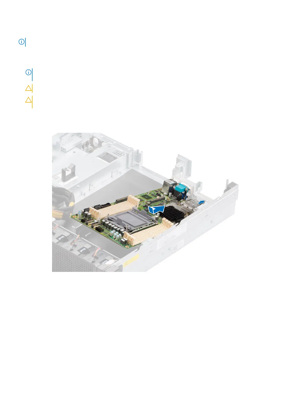
2. Holding the system board by the edges, lower the system board into the system.
3. Incline the system board at an angle and align the connectors on the system board with the slots on the I/O of the chassis
until the connectors are firmly seated in the slots.
Figure 117. Installing the system board
4. Using a Phillips #2 screwdriver, tighten the screws that secure the system board to the chassis in the sequence shown in
below image.
106
Installing and removing system components
 Loading...


