c. Expansion card riser 1
d. Drive cage
e. Expansion card riser 3
f. Memory modules
g. Processor and heat sink module
h. Internal USB memory key (if installed)
i. M.2 BOSS card
j. Disconnect all cables from the system board.
CAUTION: Take care not to damage the system identification button while removing the system board
from the system.
NOTE: The procedure to remove the system board is same for Rear Accessed and Front Accessed configurations.
Steps
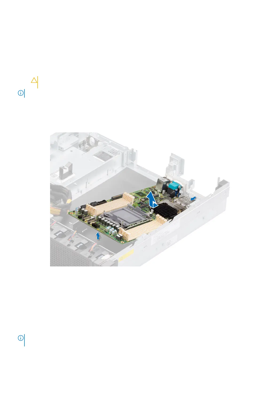
1. Using a Phillips #2 screwdriver, remove the screws that secure the system board to the chassis
2. To disengage the ports from the slots on the chassis, slide the system board toward the fan chassis.
3. Incline the system board at an angle and lift the system board out of the chassis.
Figure 116. Removing the system board
Next steps
Install the system board.
Installing the system board
Prerequisites
NOTE:
Before replacing the system board, replace the old iDRAC MAC address label in the Information tag with the iDRAC
MAC address label of the replacement system board
1. Follow the safety guidelines listed in the Safety instructions.
2. Follow the procedure listed in Before working inside your system.
Installing and removing system components
105
 Loading...


