Drives 129
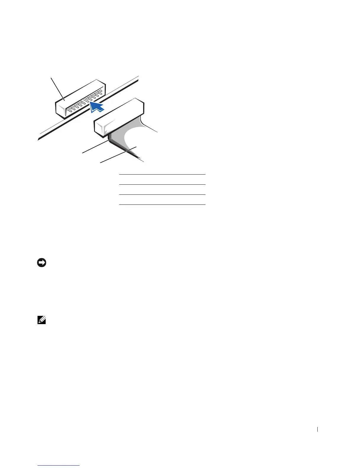
Most interface connectors are keyed for correct insertion; that is, a notch or a missing pin on
one connector matches a tab or a filled-in hole on the other connector. Keyed connectors
ensure that the pin-1 wire in the cable (indicated by the colored stripe along one edge of the
cable) goes to the pin-1 end of the connector. The pin-1 end of a connector on a board or a
card is usually indicated by a silk-screened “1” printed directly on the board or card.
NOTICE: When you connect an interface cable, do not place the colored stripe away from pin 1
of the connector. Reversing the cable prevents the drive from operating and could damage the
controller, the drive, or both.
SCSI Device Installation Guidelines
This section describes how to configure and install SCSI devices in your computer.
NOTE: The system board SCSI controller supports hard drives only. Do not connect CD or DVD
drives, tape drives, DAT drives, and so on.
SCSI ID Numbers
Internal SCSI devices must have a unique SCSI ID number from 0 to 15. If you are using
the SCSI connector on the system board and a SCSI controller card installed in your
computer, you have two separate SCSI buses operating. Each SCSI bus has a set of SCSI ID
numbers from 0 to 15.
1 interface connector
2 colored stripe on cable
3 interface cable