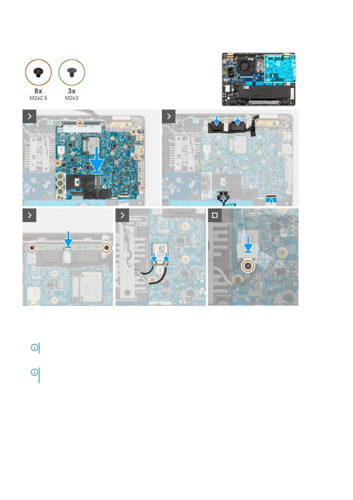
Figure 51. Installing the system board
Steps
1. Align and place the system board on its slot on the palm-rest assembly.
2. Replace the three screws (M2x2.5) that secures the system board and I/O board to the palm-rest assembly.
NOTE: Loosen the captive screws in the reverse sequential order mentioned on the heat sink [ 3 > 2 > 1].
3. Replace the five screws (M2x2.5) that secure the system board to the palm-rest assembly.
NOTE:
The USB-C connector module is part of the replacement system board but is also a service part that can be
replaced independently. See the USB-C Connector Module section for more information.
4. Connect the camera cable to the connector on the system board.
5. Connect the display cable to the display cable connector (LCD1) on the system board.
6. Route the display cable through the routing guides on the system board.
7. Adhere the black flap near the antenna cables and cover the display and camera-cable.
8. Place the display-cable bracket over the display cable and camera cable.
9. Replace the two screws (M2x2.5) that secure the display-cable bracket to the palm-rest assembly.
10. Connect the speaker cable to the connector on the system board.
11. Connect the USH cable to the USH module and close the latch to secure the cable.
100
Removing and installing Field Replaceable Units (FRUs)