NOTE: The USB-C connector module is part of the replacement system board but is also a service part that can be
replaced independently. See the USB-C Connector Module section for more information.
15. Lift the system board off the palm-rest assembly.
Installing the system board
CAUTION: The information in this installation section is intended for authorized service technicians only.
Prerequisites
If you are replacing a component, remove the existing component before performing the installation process.
About this task
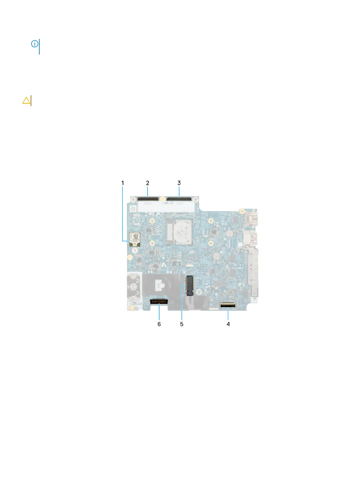
The following images indicate the system board connectors. The following images indicate the location of the system board and
provide a visual representation of the installation procedure.
Figure 50. System board
connectors
1. Wireless-card (WLAN)
2. Camera-cable connector
3. Display cable connector
4. USH cable connector
5. Solid-state drive Slot
6. Battery-cable connector (BATT1)
Removing and installing Field Replaceable Units (FRUs)
99