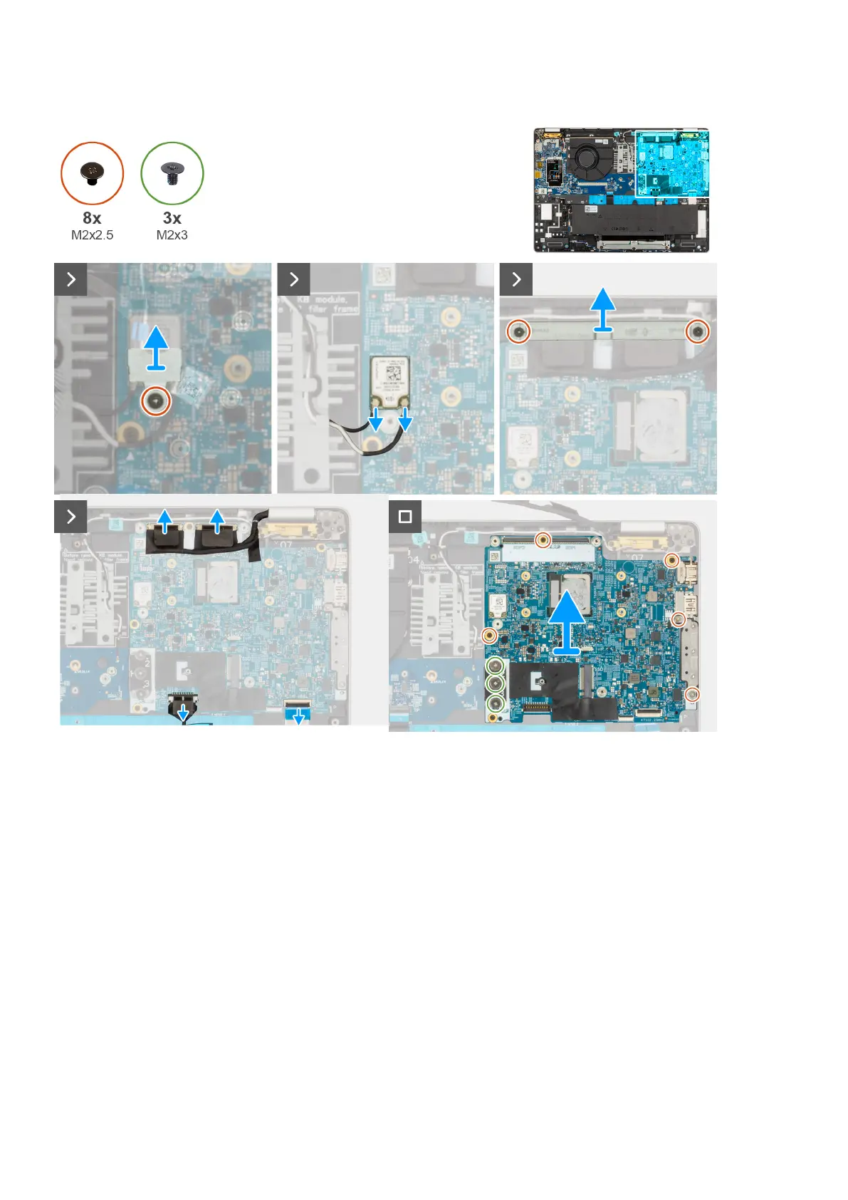
Figure 49. Removing the system board
Steps
1. Remove the screw (M2x2.5) that secure the WLAN bracket to the palm-rest assembly.
2. Lift the WLAN bracket off the palm-rest assembly.
3. Disconnect the WLAN cables from the system board.
4. Remove the two screws (M2x2.5) that secure the display cable bracket to the palm-rest assembly.
5. Lift the display cable bracket off the palm-rest assembly.
6. Lift the black flap near the antenna cables and uncover the sensor board-cable.
7. Disconnect the camera cable from the connector on the system board.
8. Disconnect the display cable from the display cable connector (LCD1) on the system board.
9. Remove the display cable from the routing guides on the system board.
10. Disconnect the speaker cable from the system board.
11. Touchpad is connected to I/O board .
12. Open the latch and disconnect the USH cable from the USH module.
13. Remove the three screws (M2x3) that secures the system board and I/O board to the palm-rest assembly.
14. Remove the five screws (M2x4) that secure the system board to the palm-rest assembly.
98
Removing and installing Field Replaceable Units (FRUs)