EasyManua.ls Logo

Delta Electronics DVP15MC11T User Manual

Delta Electronics DVP15MC11T
601 pages
To Next Page IconTo Next Page
To Previous Page IconTo Previous Page
Page #224 background imageLoading...
Page #224 background image
Chapter 8 Logic Instructions
8_
The rule that Bit-string data are converted into Boolean data is as the following table shows.
Data type
The value of In corresponds to the value of Out
In
Out
In
Out
BYTE BOOL
16#00
FALSE
16#01~16#FF
TRUE
WORD BOOL
16#0000
FALSE
16#0001~16#FFFF
TRUE
DWORD BOOL
16#0000_0000
FALSE
16#0000_0001~16#FFFF_FFFF
TRUE
LWORD BOOL
16#0000_0000_0000_0000
FALSE
16#0000_0000_0000_0001~
16#FFFF_FFFF_FFFF_FFFF
TRUE
Bit string to Bit string
Bit-string data can be converted to Bit-string data. And some instructions are shown below.
There are two kinds of conversion for different types of bit-string data. One is the conversion of
the less-length data to the greater-length data. The other is the conversion of the greater-length
data to the less-length data.
The less-length data is converted to the greater-length data by writing the values of all bits of
the less-length data to corresponding bits of the greater-length data and setting the values of
the remaining bits of the greater-length data to 0.
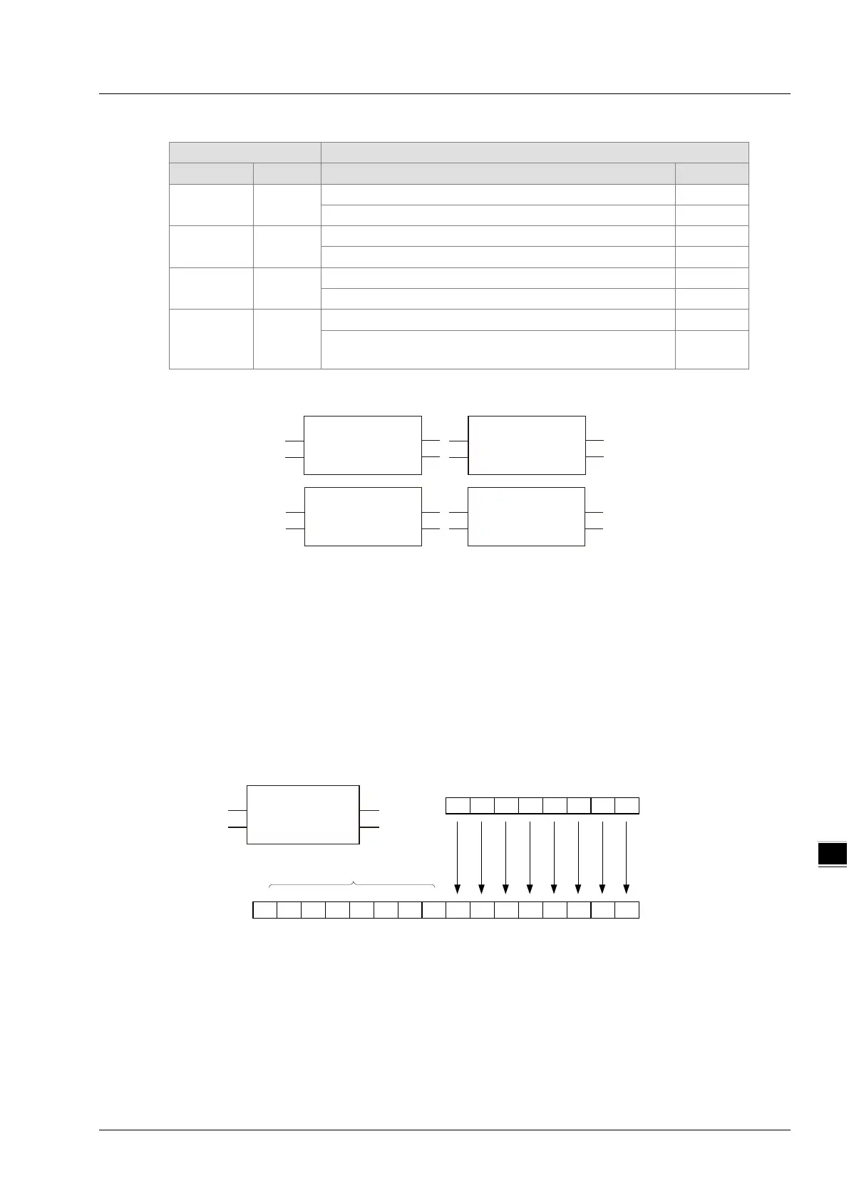
See the following example that the Byte data in In is converted to the Word data in Out. The
values of Bit0~Bit7 of In are copied and pasted to Bit0~Bit7 of Out. And the values of Bit8~Bit15
of Out are set to 0.
The greater-length data are converted to the less-length data by revising the values of all bits of
the less-length data into the values of the corresponding bits of the greater-length data and the
values of the remaining bits of the greater-length data are not converted and have no impact on
the conversion.
See the following example that the Word data In is converted to the Byte data Out. The values
of Bit0~Bit7 of In are copied and pasted to Bit0~Bit7 of Out. And the values of Bit8~Bit15 of In
are not converted and have no impact on the conversion.
BYTE_TO_WORD
EN ENO
Out
In
WORD_TO_BYTE
EN ENO
Out
In
DWORD_TO_WORD
EN ENO
Out
In
LWORD_TO_BYTE
EN ENO
Out
In
BYTE_TO_WORD
EN ENO
OutIn
10101101
00000000
Bit0Bit7
In
Out
Fill 0
The less-length data are converted
to the greater-length data
10101101
Bit8Bit15
BYTE
WORD
8-153

Table of Contents

Question and Answer IconNeed help?

Do you have a question about the Delta Electronics DVP15MC11T and is the answer not in the manual?

Delta Electronics DVP15MC11T Specifications

General IconGeneral
BrandDelta Electronics
ModelDVP15MC11T
CategoryController
LanguageEnglish

Summary

Chapter 1 Preface

1.1 Explanation of Symbols in This Manual

Explains symbols used for warnings and cautions in the manual to prevent injury and damage.

1.2 Revision History

Provides a history of manual revisions, including version, revision details, and release dates.

Chapter 2 Overview of DVP15MC11T

2.1 Product Description

Describes the DVP15MC11T motion controller, its features, protocols, and applications.

2.2 Functions

Lists the key functions and capabilities of the DVP15MC11T, including axis control, processor, and communication ports.

2.3 Profile and Components

Details the physical profile and identifies various components of the DVP15MC11T controller.

Chapter 3 Specifications

3.1 Function Specifications

Details functional specifications including programming capacity, motion control limits, and built-in ports.

3.2 Electrical Specifications

Outlines electrical specifications such as power voltage, consumption, isolation, and environmental immunity.

Chapter 4 System Architecture

4.1 System Constitution

Describes how the DVP15MC11T enables a multi-layer industrial network with various communication protocols.

4.3 Left-side Extension

Lists connectable left-side extension modules, including analog and network modules.

4.4 Right-side Extension

Lists connectable right-side extension modules, including digital, analog, and temperature modules.

4.6 SD Memory Card

Details the specifications, classification, and usage of SD memory cards for firmware upgrades.

Chapter 5 Installation

5.1 Dimensions

Provides the profile and detailed dimensions of the DVP15MC11T and its extension modules.

5.2 Installing the Module in the Control Cabinet

Explains the DIN rail installation, cabinet illustration, and environmental requirements for the module.

Chapter 6 Wiring, Communication Setting and Network Construction

6.1 Wiring

Covers power supply specifications and safety circuit wiring recommendations for the DVP15MC11T.

6.3 RS-485 Communication Port

Details the functions, pin definitions, hardware connection, and supported protocols for the RS-485 port.

6.4 RS-232 Communication Port

Describes the functions, pin definitions, hardware connection, and supported protocols for the RS-232 port.

6.7 Ethernet Communication Port

Explains the two Ethernet ports, their functions, IP address settings, and network connection.

6.9 CANopen Communication Port

Details CANopen functions, pin descriptions, PDO mapping, and network topology.

Chapter 7 Execution Principle of DVP15MC11T Controller

7.1 Tasks

Explains the concept of tasks, their types (Cyclic, Freewheeling, Event-triggered), and priority levels.

7.4 Synchronization Cycle Period Setting

Discusses the importance of synchronization cycle period setting for bus motion control and provides calculation formulas.

Chapter 8 Logic Instructions

8.1 Table of Logic Instructions

Lists various logic instructions categorized by instruction set, including sequence, data movement, and comparison.

8.3 Sequence Input /Output Instructions

Explains instructions like R_TRIG and F_TRIG for detecting rising and falling edges of input signals.

8.4 Data Movement Instructions

Details instructions for moving data, such as MOVE, MoveBit, TransBit, and MoveDigit.

8.5 Comparison Instructions

Explains instructions for comparing values, including LT, LE, GT, GE, EQ, and NE.

8.8 Math Instructions

Covers arithmetic instructions such as ADD, SUB, MUL, DIV, MOD, and trigonometric functions.

8.10 Shift Instructions

Explains instructions for bit manipulation, including SHL, SHR, ROL, and ROR.

8.11 Selection Instructions

Details instructions for selecting values based on conditions, such as MAX, MIN, SEL, and MUX.

8.12 Data Type Conversion Instructions

Explains instructions for converting data between different types, like BOOL_TO_*** and INT_TO_***.

8.13 CANopen Communication Instructions

Details instructions for CANopen communication, including reading and writing parameters.

8.14 String Processing Instructions

Explains instructions for manipulating strings, such as CONCAT, DELETE, INSERT, LEFT/RIGHT, MID, REPLACE, LEN, FIND.

8.15 Immediate Refresh Instructions

Covers instructions for immediate refresh of input and output points, such as FROM and TO.

Chapter 9 Introductions of Axis Parameters

9.1 Description of Axis Parameters

Details various parameters related to axis configuration, including Name, Node ID, Axis type, and Modulo.

Chapter 10 Motion Control Function

10.1 EN and ENO

Explains the EN (Enable) and ENO (Enable Output) parameters used in motion control instructions.

10.2 Relation among Velocity, Acceleration and Jerk

Describes the relationship between velocity, acceleration, deceleration, and jerk in motion control.

10.3 Introduction of BufferMode

Explains the six buffer modes for sequencing motion instructions and their effects on axis behavior.

10.4 The State Machine

Illustrates the state machine for controlling each axis and the transitions between states based on motion instructions.

Chapter 11 Motion Control Instructions

11.3 Single-axis Instructions

Details instructions for controlling a single axis, including MC_Power, MC_MoveVelocity, MC_Halt, MC_Stop.

11.4 Multi-axis Instructions

Explains instructions for coordinating multiple axes, such as MC_GearIn, MC_CombineAxes, MC_CamIn.

11.5 Application Instructions

Covers application-specific instructions like Rotary Cut Technology and Electronic Cam functions.

Chapter 12 Troubleshooting

12.1 Explanation of LED Indicators

Explains the meaning of LED indicators for PWR, RUN, ERR, CANopen, Motion, and SD card states.

12.2 Table of Error IDs in Motion Instructions

Lists motion instruction error codes (hex/decimal), meanings, and corresponding correction actions.

12.3 System Trouble Diagnosis through System Error Codes

Provides a comprehensive table of system error codes, their explanations, and correction procedures.

Appendix A Modbus Communication

A.1 Message Format in ASCII Mode

Describes the communication data structure and character encoding for Modbus ASCII mode.

A.2 Message Format in RTU Mode

Details the communication data structure, including start, address, function code, data, and CRC for Modbus RTU mode.

A.3 Modbus Function Codes Supported

Lists the Modbus function codes supported by the DVP15MC11T for reading and writing registers.

A.5 Introduction to Modbus Function Codes

Explains the data structure of Modbus request and response messages for various function codes.

A.6 Table of Registers and Corresponding Modbus addresses

Maps DVP15MC11T registers (input, output, word) to their corresponding Modbus addresses and attributes.

Appendix B Modbus TCP Communication

B.1 Modbus TCP Message Structure

Explains the structure of Modbus TCP messages, including transaction identifier, protocol identifier, and data length.

B.2 Modbus Function Codes Supported in Modbus TCP

Lists the Modbus function codes supported for Modbus TCP communication.

B.3 Exception Response Code in Modbus TCP

Details the exception response codes used in Modbus TCP communication.

B.4 Modbus Function Codes in Modbus TCP

Explains Modbus function codes for reading and writing registers in Modbus TCP.

B.5 Registers in DVP15MC11T and Corresponding Modbus Addresses

Provides a table mapping DVP15MC11T registers to their corresponding Modbus addresses.

Appendix C CANopen Protocol

C.1 Node States

Describes the different node states within a CANopen network: Initializing, Pre-operational, Operational, and Stop state.

C.3 PDO (Process Data Object)

Details the Process Data Object (PDO) in CANopen communication, including its purpose and transmission modes.

C.4 SDO (Service Data Object)

Explains the Service Data Object (SDO) used for client/server communication in CANopen for accessing the object dictionary.

Appendix D Explanation of Homing Modes

D.1 Explanation of Homing Modes

Explains various homing modes dependent on limit switches and Z pulse for axis positioning.

Appendix E List of Accessories

E.1 Accessories for CANopen Communication

Lists accessories for CANopen communication, including cables, distribution boxes, and terminal resistors.

E.2 Accessories for PROFIBUS DP Communication

Lists accessories for PROFIBUS DP communication, including connectors and cables.

E.3 Accessories for DeviceNet Communication

Lists accessories for DeviceNet communication, including cables and distribution boxes.

Related product manuals