Chapter 8 Logic Instructions
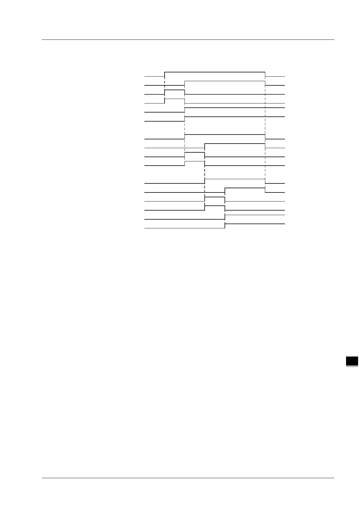
Timing Chart
The first DMC_ReadParameter_CANopen starts being executed as ReadPm_C1_Ex changes
from FALSE to TRUE. When the execution of the first DMC_ReadParameter_CANopen is
completed, ReadPm_C1_Done changes to TRUE, ReadPm_C1_DaTy = 2 and
ReadPm_C1_Dat=5000.
That is, the content of the servo slave parameter P1-55 which is read is 5000. (The maximum
speed of the servo is limited to 5000rpm.)
As ReadPm_C1_Done changes from FALSE to TRUE, DMC_WriteParameter_CANopen starts
being executed. When the DMC_WriteParameter_CANopen instruction execution is completed,
WritePm_C_Done changes to TRUE. That is, 1000 is written as the content of the servo slave
parameter P1-55. (The maximum speed of the servo is limited to 1000rpm.)
The second DMC_ReadParameter_CANopen is executed as WritePm_C_Done changes from
FALSE to TRUE. When the execution of the second DMC_ReadParameter_CANopen is
completed, ReadPm_C2_Done changes to TRUE, ReadPm_C2_DaTy = 2 and
ReadPm_C2_Dat=1000. That is, the read content of the servo slave parameter P1-55 is 1000.
(The maximum speed of the servo is limited to 1000rpm.)
ReadPm_C1_Ex
ReadPm_C1_Done
ReadPm_C1_Bsy
ReadPm_C1_Act
ReadPm_C1_DaTy
ReadPm_C1_Dat
ReadPm_C1
ReadPm_C1_Done
WritePm_C_Done
WritePm_C_Bsy
WritePm_C_Act
WritePm_C
WritePm_C_Done
ReadPm_C2_Done
ReadPm_C2_Bsy
ReadPm_C2_Act
ReadPm_C2_DaTy
ReadPm_C2_Dat
ReadPm_C2
8-181