DVP15MC11T Operation Manual
Function Data type
Mode 1: The trigger signal comes from
the falling edge of one of the
input points: I0~I7 and I10~I17
specified by TriggerInput
captured position is converted
from the number of pulses that
the external encoder port of the
controller receives through
parameters.
Mode 2: The trigger signal comes from
the rising edge of the high-
input point: DI7 of the
drive. The captured
converted from
the number of
pulses which the servo motor
feeds back to the servo drive
through axis parameters.
Mode 3: The trigger signal comes from
the rising edge of the high-
speed
input point: DI7 of the servo
drive. The captured
converted from
pulses that
drive receives through
parameters.
Mode 4: The trigger signal comes from
the rising edge of the high-
speed
input point: DI7 of the servo
drive. The captured
converted from
pulses that
drive receives through
Mask Reserved - - -
Notes:
1. In Mode 0 and mode 1, the same input point cannot be used for the position capture simultaneously.
2. In Mode 2, mode 3 and mode 4, the position capture cannot be performed for the same axis
simultaneously.
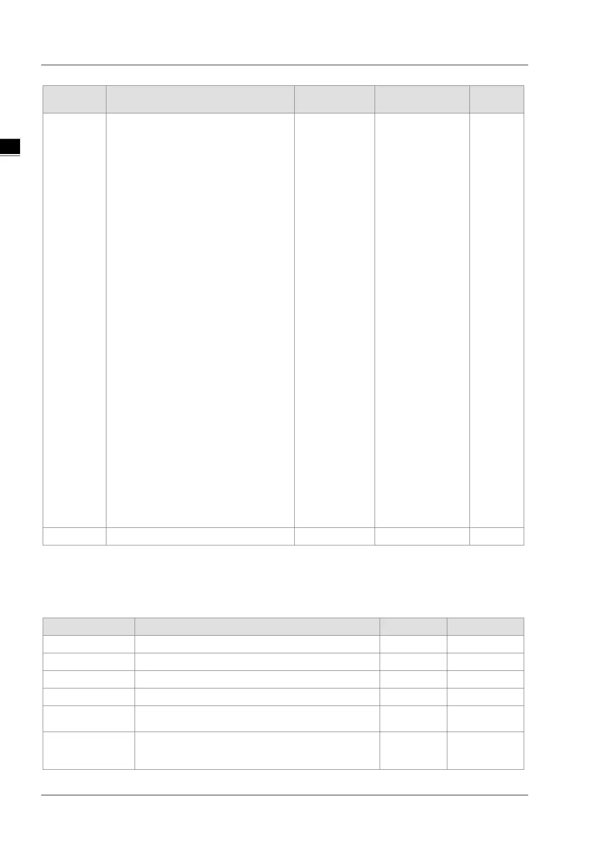
Output Parameters
Parameter name Function Data type Valid range
Done TRUE when the instruction execution is completed. BOOL TRUE / FALSE
Busy TRUE when the instruction is being executed. BOOL TRUE / FALSE
Active TRUE when the axis is being controlled. BOOL TRUE / FALSE
CommandAborted
TRUE when the instruction is aborted.
BOOL TRUE / FALSE
Error
TRUE when there is an error in the execution of the
instruction.
BOOL TRUE / FALSE
ErrorID
Contains error codes when an error occurs. Please
refer to section 12.2 for the corresponding error code.
WORD
11-120
 Loading...
