Chapter 12 Troubleshooting
1
Parameter name Function Data type Valid range
RecordedPosition
The captured position after the completion of the
instruction execution. Refer to the following Function
LREAL
Output Update Timing
Name Timing for changing to TRUE Timing for changing to FALSE
Done
When the instruction execution is
completed.
When Execute changes from TRUE to
FALSE
Busy When Execute changes to TRUE.
When Done changes to TRUE.
When Error changes to TRUE.
When CommandAborted changes to
Active When Execute changes to TRUE.
When Done changes to TRUE.
When Error changes to TRUE.
When CommandAborted changes to
TRUE.
CommandA
borted
When the instruction execution is aborted
by some other motion control instruction.
When Execute changes from TRUE to
FALSE
CommandAborted is set to TRUE when
the instruction execution is aborted after
Execute changes from TRUE to FALSE
during the instruction execution. One
period later, CommandAborted changes
Error
When an error occurs in the instruction
execution or the input parameters for the
When Execute changes from TRUE to
FALSE
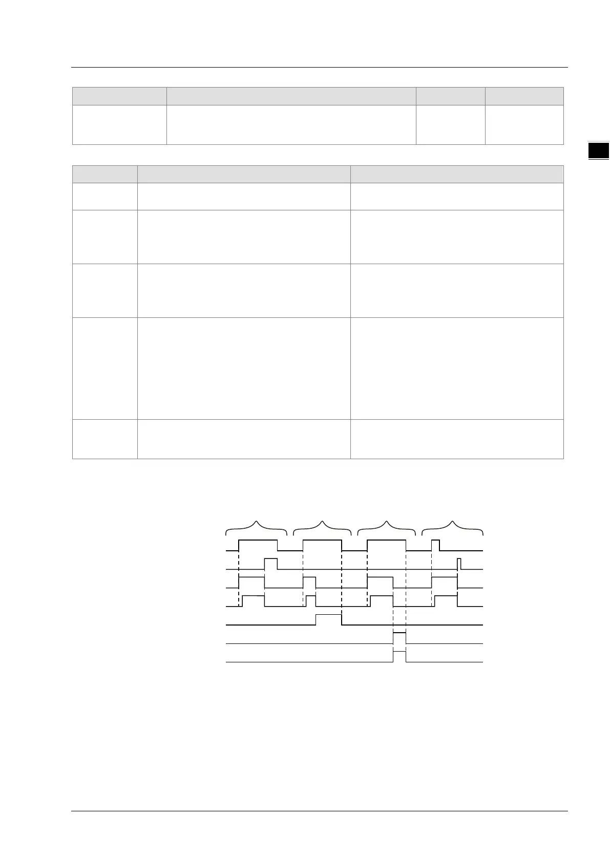
Output Update Timing Chart
Case 1: When Execute changes from FALSE to TRUE, Busy changes to TRUE and one period later,
Active changes to TRUE. When positioning is completed, Done changes to TRUE and
meanwhile Busy and Active change to FALSE.
Case 2: When Execute changes from FALSE to TRUE and the instruction is aborted by other instruction,
Commandaborted changes to TRUE and meanwhile Busy and Active change to FALSE. When
Execute changes from TRUE to FALSE, CommandAborted changes to FALSE.
Execute
Done
Busy
Active
CommandAborted
Error
Case1
Case2
Case3
Case4
Error ID
11-121