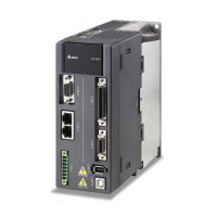
DVP15MC11T Operation Manual
Case 3: After Execute changes from FALSE to TRUE, Error changes to TRUE and ErrorID shows
corresponding error codes when an error occurs such as axis alarm or Offline. Meanwhile, Busy
and Active change to FALSE. Error changes to FALSE when Execute changes from TRUE to
FALSE.
Case 4: During execution of the instruction, Done changes to TRUE when the instruction execution is
completed after Execute changes from TRUE to FALSE. Meanwhile, Busy and Active change to
FALSE and one period later, Done changes to FALSE.
Function
(RecordedPosition) the position that DMC_TouchProbe captures is converted from other value
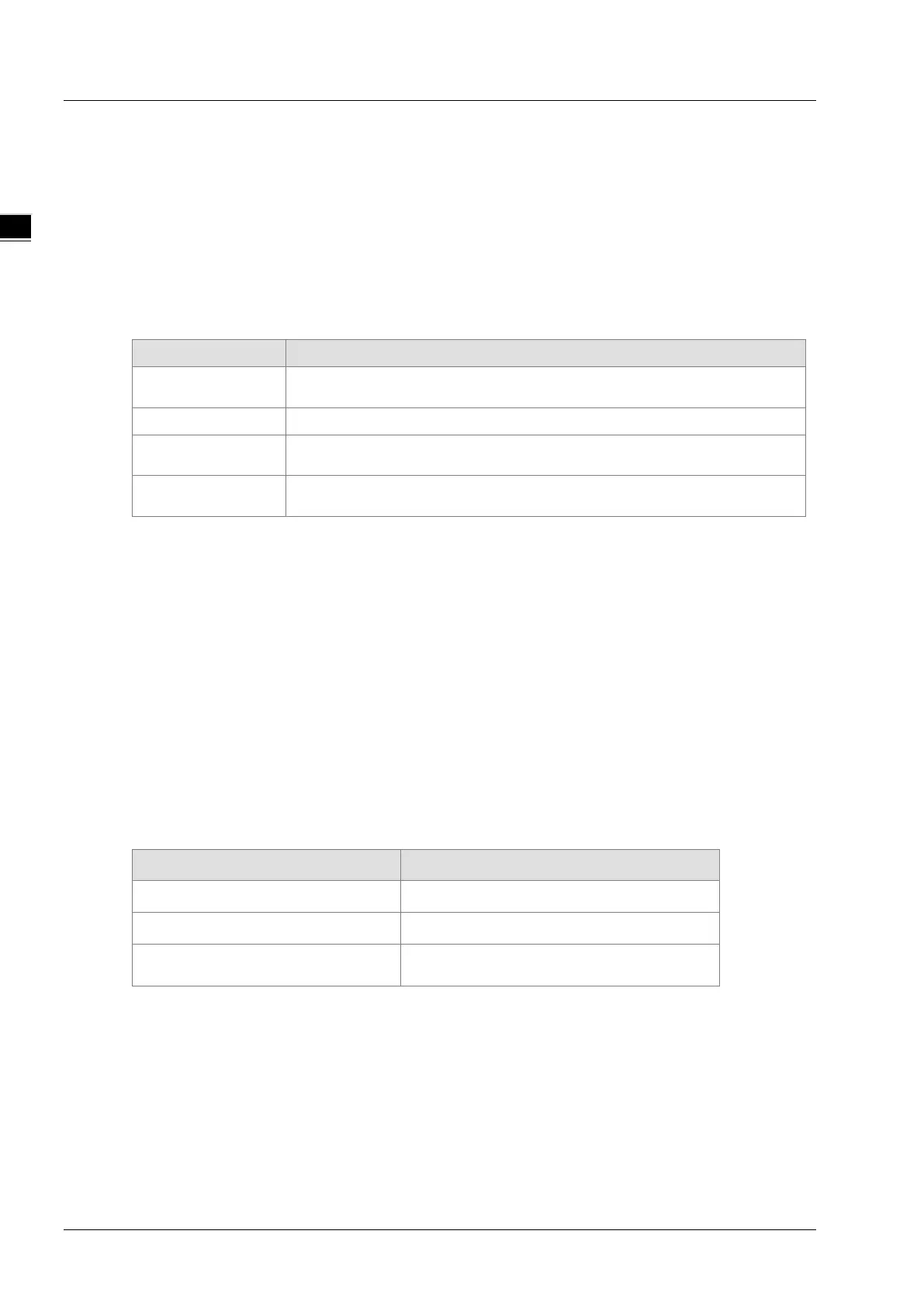
based on axis parameters. The data sources for conversion are listed in the following table.
Mode 0 and mode 1
The number of pulses that the external encoder port of DVP15MC11T
receives
Mode 2 The number of pulses that the servo motor feeds back to the servo drive
Mode 3
The number of pulses that the pulse, /pulse, sign and /sign input terminals
of CN1 port of the servo drive receive.
Mode 4
The number of pulses that A, /A, B and /B input terminals of CN5 port of
the servo drive receive.
For mode 0, 1 or 2, the range of the data source value is -2147483648~2147483647. When
the data source value exceeds 2147483647, it will become -2147483648. With the changing +
or – sign of the data source value, the + or - sign of the value of RecordedPosition will not
change but the value of RecordedPosition will continue to increase.
For mode 3 or 4, the range of the data source value is -2147483648~2147483647. When the
data source value exceeds 2147483647, it will become -2147483648. The value of
RecordedPosition will change from a positive number to a negative number.
The position captured by the DMC_TouchProbe instruction is calculated according to axis
parameters. For different modes, the data sources are different. “Servo gear ratio setting” and
“Mechanism gear ratio setting” in axis parameters are shown in the following table. When Mode
value of the instruction is equal to 3 (which you can refer to the introduction of mode 3 below), the
number of pulses received at pulse, /pulse, sign and /sign of CN1 is 435 and the position captured
by the instruction is 65.25. The calculation formula: 435×(3×1000)÷(2×10000)=65.25. 10000,
2, 3 and1000 in the formula correspond to 10000, 2, 3, and 1000 in the following table respectively.
For other mode, the calculation method for the position captured by the instruction is the same as
that described above but only the data source is different.
Servo gear ratio setting Mechanism gear ratio setting
Unit Numerator: 128
Output rotations of gear: 3
Unit Denominator: 1
Input rotations of gear: 2
Pulses per rotation:10000
Units per output rotation: 1000
units/rotation
When Mode=0 or 1 in DMC_TouchProbe, the captured position can be calculated according to the
method mentioned above as well. In actual application, the position capture is generally performed
by building an external encoder axis. When the number of pulses received at the external encoder
interface of DVP15MC11T is 638, the position captured by DMC_TouchProbe is 95.4. The
calculation formula: 638×(3×1000)÷(2×10000)=95.4. In the formula, 1000 is Units per output
rotation, 2 is Input rotations of gear; 3 is Output rotations of gear and 10000 is number of pulses
per rotation). When I0 changes from OFF to ON once, the position capture is performed once.
11-122
 Loading...
