Chapter 12 Troubleshooting
1
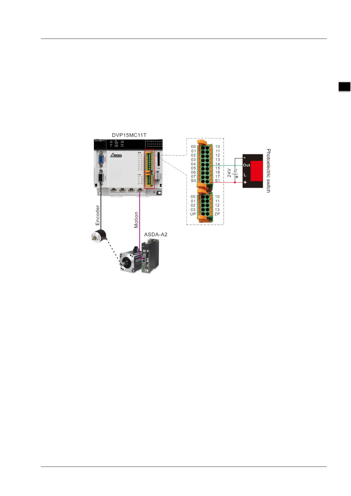
Wiring Figure
Mode 0 and mode 1
Mode 0: The external signal triggers I point of DVP15MC11T and the position capture is conducted
through the rising edge of the input point specified by TriggerInput. The captured position is
converted from the number of pulses the external encoder port of the controller receives
through axis parameters.
Mode 1: The external signal triggers I point of DVP15MC11T and the position capture is conducted
through the falling edge of the input point specified by TriggerInput. The captured position is
converted from the number of pulses the external encoder port of the controller receives
through axis parameters.
Mode 2
The external signal triggers the high-speed input point: DI7 of the servo drive. The position captured is
converted from the number of pulses which the servo motor feeds back to the servo drive through axis
parameters.
11-123