AS Series Module Manual
14-6
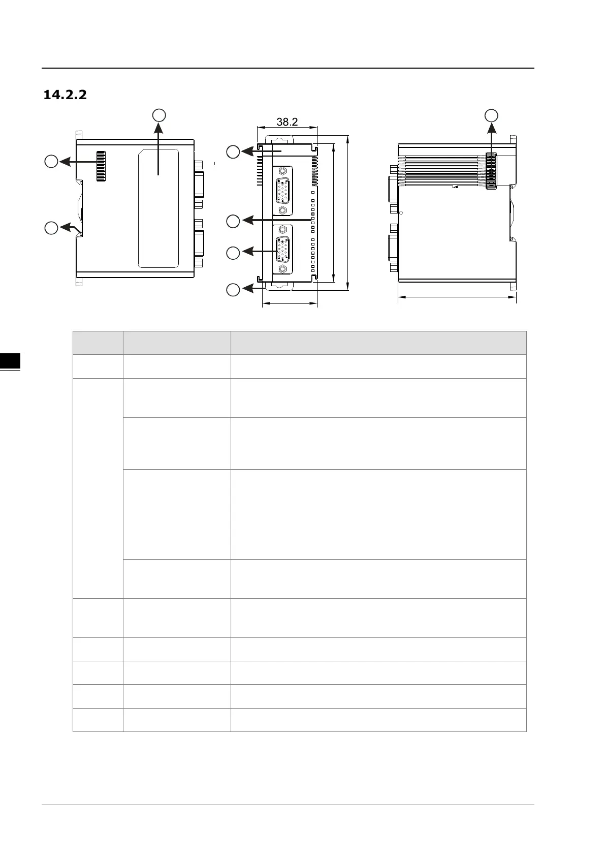
Profile
Number Name Description
1
Model name
Model name of the module
2
POWER LED indicator
Indicates the status of the power supply
ON: The power is on.
Error LED indicator
Error status of the module
ON: A serious error occurs in the module.
OFF: The module is normal.
Blinking: A minor error occurs in the module.
Counter LED indicator for
Ch1 Act. & Ch2 Act.
Counting status of the module (Green)
OFF: The counter is disabled.
When the pulse input takes place:
ON: The counter is enabled but the result of counting is not changed.
Blinking: The result of counting is updating.
When the SSI input takes place:
Blinking: The counter is enabled and the position value is updating.
Input / output LED
indicator
ON: Receives an input / output signal
OFF: Receives no input / output signal
Refer to section 14.2.8 for details.
3 D-sub15
Input: Connected for pulse input and encoder
Output: Connected to loads to be driven
Power: Providing external encoder +5 VDC
4 DIN rail clip Secures the module onto the DIN rail
5 Extension module port Connects extension modules
6 Ground clip
For Grounding
7 Label
Nameplate
 Loading...
