Chapter 4 Installing Hardware
4-55
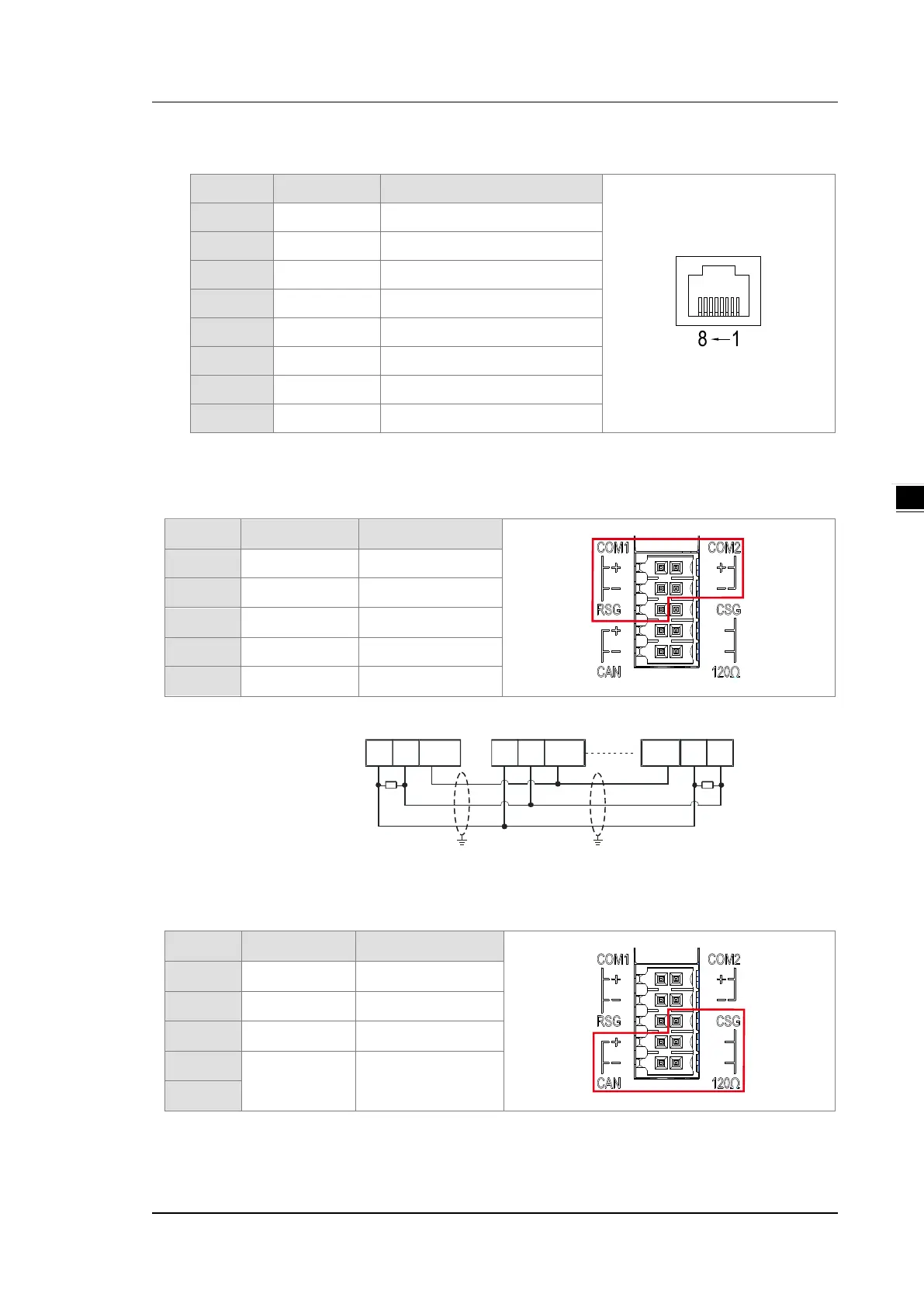
Ethernet port
Pin Signal Description
1 TX+ Transmitting data (positive pole)
2 TX- Transmitting data (negative pole)
3 RX+ Receiving data (positive pole)
4 -- N/C
5 -- N/C
6 RX- Receiving data (negative pole)
7 -- N/C
8 -- N/C
RS-485 Pins and Wiring
RS485 Pins
Pin Signal Description
1 + COM1 D+
3 - COM1 D-
5 RSG Signal Ground
2 + COM2 D+
4 - COM2 D-
RS-485 Wiring
D+ D- RSG
D+ D- RSG RSG D+ D-
Master Slave Slave
Terminal
resistor
(120 ohm)
Shielded
cable
Shielded
cable
CAN Pins and Wiring
CAN Pins
Pin Signal Description
7 CAN+ CAN_H
9 CAN- CAN_L
6 CSG GROUND
8
120Ω Terminal resistor
10
Note: Pin8 and Pin10 must be short-circuited to activate the built-in terminal resistor 120Ω and work as an
impedance to reduce noise inference when signal reflections occur and ensure signal can be transmitted
normally.

 Loading...


