Chapter 2 Specifications and System Configuration
2-23
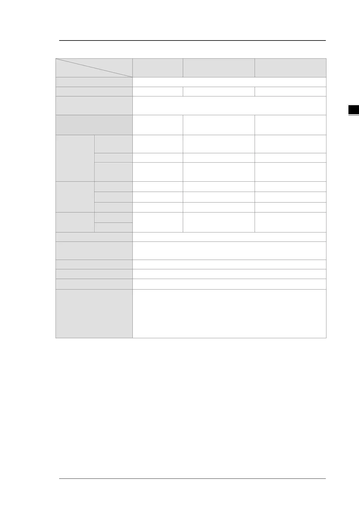
Electrical specifications for the outputs on DVP-SV3/SX3 Series.
Model
DVP28SV311R
DVP28SV311T
DVP28SV311S
Removable terminal blocks
Number of digital outputs
SV3: 12 points (Y0~Y7, Y10~Y13)
Voltage
10~250VAC;
5~30VDC
5~30 VDC 5~30 VDC
Maximum
load
Resistance
1.5A/output,
0.5A 0.5A
3
Bulb
20W (24 VDC)
N/A N/A
Switching
frequency
*1
Response
10ms 2.5μs 2.5μs
Analog output conversion
4
2 ms / channel (applicable to SX3)
12-bit (applicable to SX3)
-10 V~10 V/0~20 mA (applicable to SX3)
Coupling Voltage:1KV
Analog output isolation
An analog
circuit is isolated from a digital circuit by a digital integrated circuit/an
optocoupler, but the analog channels are not isolated from one another.
Isolation between a digital circuit and a ground: 500 VAC
Isolation between an analog circuit and a ground: 500 VAC
Isolation between an analog circuit and a digital circuit: 500 VAC
Isolation between the 24 VDC and a ground: 500 VAC
*1: The scan cycle affects the frequency.
*2: UP, ZP should include external aid power 24VDC (-15% ~ +20%) and the rated consumption is around
1mA/point.
*3: Life cycle curve: The lifetime of a relay terminal varies with the working voltage, the load type (the power
factor cosψ, the time constant t(L/R)), and the current passing through the terminal. The relation is shown in
the life cycle curve below. The life cycle curve is shown below.

 Loading...


