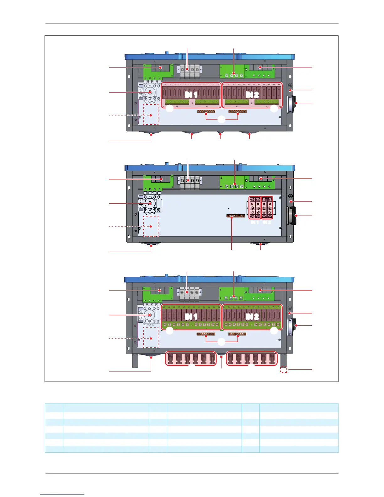
Table 2-3: Wiring box layout description
Figure 2-7:Wiring box layouts
ComponentNO. NO.
2” cable opening for AC
½” cable opening for DC grounding
DC terminal for IN 1
DC terminal for IN 2
Component
7
8
12
NO. Component
Type II DC SPD
Internal AC terminal
13
17
Communication port
Grounding (M6 threaded stud)
18 External ground bar location
1
2
Fuse holder type DC IN1
9
Internal DC terminal
14
3
Fuse holder type DC IN2
10
15
4
DC switch
11
16
MC4 connectors (12 pairs)
5
6
AC switch
2” cable opening for DC
DC grounding bar Type II AC SPD
IN 1
IN 2
IN 1 IN 2
-120 Model WB
-121 Model WB
-122 Model WB
⑰
⑩
⑩
⑫
⑬ ⑭
①
①
④
⑪
⑪
②
②
③ ③
⑰
⑫
③⑤
⑥ ⑦
④
④
⑬ ⑭
⑰
⑩
⑱
⑯
⑮⑯⑮
⑫
⑬ ⑭
①
⑪
IN 1IN 1 IN 2IN 2
IN 1IN 1 IN 2IN 2
⑨⑧
⑥
⑤
⑥
⑤
⑩
⑨
⑨
⑧ ⑩
⑨
⑯
⑯
⑯
22
Introduction