• These models are designed to be utilized with external combiner boxes and
are not provisioned with internal DC combining capability.
• Specific size of DC conductors must be determined from NEC or other local
codes.
•
The range of conductor sizes accommodated by each DC terminal is 8~2 AWG.
• Ensure the correct conductor is connected to its associated terminal.
•
Tighten each terminal block screw to a torque value of 8AWG
-
40lbf-in (4.5N.m)
; 6~2 AWG
-
110 lbf-in (12.4 N.m).
• The bending space is 160 mm [6.3in] which meets the safety standard.
• For the 121 model, two mounting options for installing the DC connection are
available, bottom or side entry; both options have a 2" chassis access hole
(KO). Side entry is shown in Figure 3-14.
Please read the following instructions for attaching DC terminals (121 models):
3.4.2 DC Wiring Installation for 121 models
Ensure the DC terminal block screws are tightened to a torque value of
8AWG
-
40 lbf-in (4.5 N.m)
6~2AWG
-
110 lbf-in (12.4 N.m)
- For aluminum cable :
Min./max. Conductor cross-section 10 / 33.6 mm
2
Tightening torque 110 lbf-in (12.4 N.m)
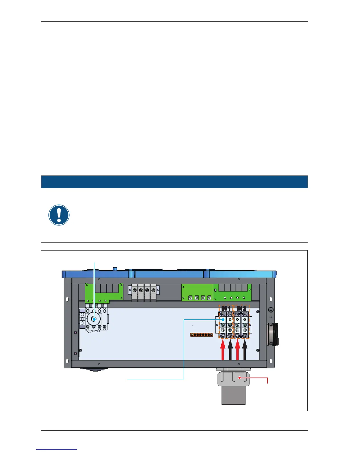
ATTENTION
Figure 3-14: Location for DC terminals for 121 models
IN 1 IN 2IN 1 IN 2
DC Terminals
Stripping length: 17mm [0.67in]
Conductor cross-section: 8~2AWG(8~33.6mm²)
Torque: 8AWG
-
40 lbf-in (4.5 N.m)
6~2AWG
-
110 lbf-in (12.4 N.m)
AC Switch
EMT
2" cable gland for
DC with EMT
39
Installation