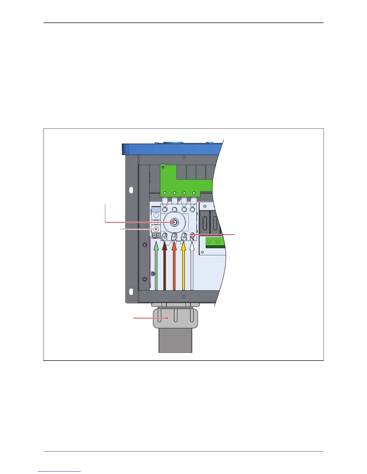
Figure 3-12 illustrates the location of the AC conduit entry and connections for
AC terminal block:
- Open all AC switch cage-clamps as noted in Section 3.3.4
- Ensure the correct conductor is connected to the appropriate terminal.
- After conductor is inserted, tighten L1~N terminal with a torque value of 24
lbf-in (2.8 N.m), PE terminal with 31 lbf-in (3.5 N.m).
3.3.5 AC Wiring for all models
Figure 3-12: Location of AC terminals and wiring (all versions)
Torque 24 lbf-in (2.8 N.m)
to fix the screw
AC switch (Terminal)
31 lbf-in (3.5 N.m)
to fix the screw
2" cable gland for AC
with EMT
EMT
36
Installation