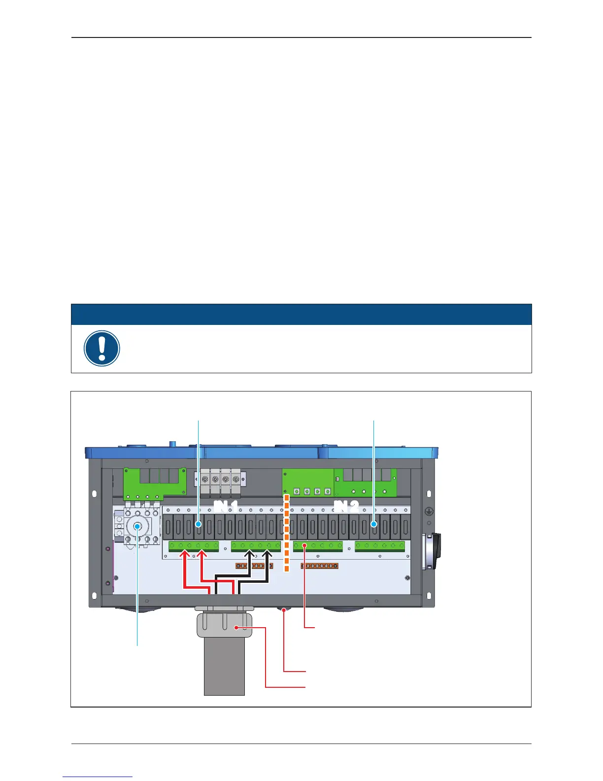
Figure 3-13: Location for DC terminals for 120 models
IN 1
IN 2
IN 1 IN 2
EMT
1½ " cable gland for DC with EMT
Stripping length: 10~11mm [0.40~0.43in]
Conductor cross-section: 12~10 AWG (4~6 mm²)
Torque 16 lbf-in (1.8 N.m) to fix the screw
½" Opening for PE
2" cable gland for DC with EMT
- Ensure all fuse holder terminals are tightened to the specified torque value of
16 lbf-in (1.8 N.m).
ATTENTION
• Ensure the DC conductors used are Cu and sized to the correct ampacity per
NEC or other local code
• Strip off all wires for 10~11 mm [0.4~0.43 in].
• The cross-sectional area for each DC conductor is 12~10 AWG.
• Ensure the fuse holder terminal clamp is open
• Ensure correct conductor is connected to the correct fuse holder.
• Tighten each individual screw terminal screw to a torque value of 16 lbf-in
(1.8 N.m).
• Two 2” chassis access holes (KOs) can be utilized to connect conduits from
PV array DC wiring into the inverter, as shown in Figure 3-13.
• 120 models is compatible with 1000V/20A UL listed fuse.
Please read the following instructions for connecting DC terminals (120 models):
3.4.1 DC Wiring Installation for 120 models
AC Switch
Input 1 Fuse holders Input 2 Fuse holders
38
Installation