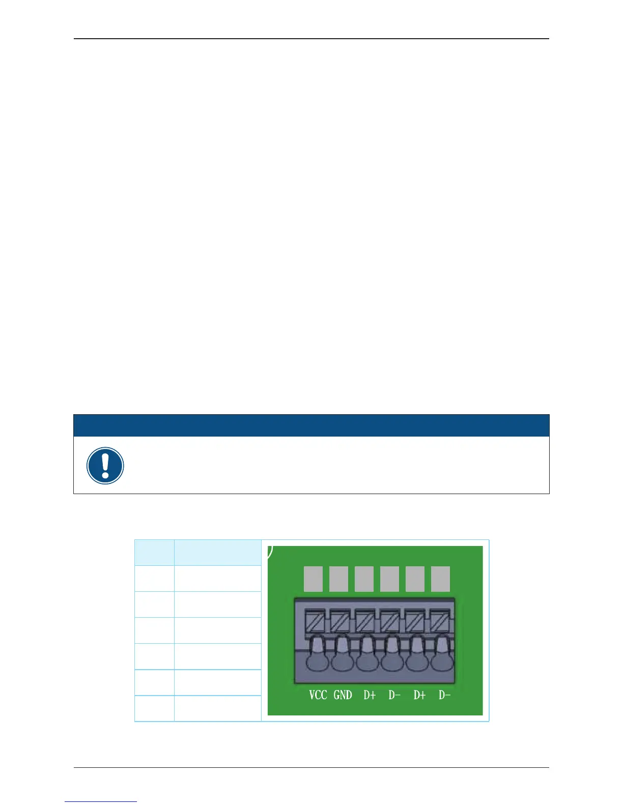
The pin definition for the RS-485 terminal block is shown in
Table 3-1.
- Pins 1 and 2
provide a 12DC bus for use with accessories such as R3 Power Monitor.
- Pins 3 and 5 are both connected to the DATA+ input.
- Pins 4 and 6 are both connected to the DATA
-
input.
These connections allow easy daisy-chaining of multiple inverters.
A 120 ohm bus termination resistor and associated control switch are located
on the communication board (See Figure 3-20) The switch function is as shown
in Table 3-2.
Different RS-485 connection scenarios require different set up for the 120 ohm
bus termination resistor.
•
When several inverters are cascaded (i.e., "daisy-chained") only the last inverter
in the chain must have its bus termination resistor switched ON. Refer to
Figure 3-22.
•
If the length of any RS-485 bus is greater than 2000' (610m), the use of Belden
3105A cable (or eq.) is recommended to insure communication quality.
(When using R3 Monitor, a 4-wire cable is required; Belden 3108A (or eq.) is
recommended.)
3.5.2 RS-485 Connection
Pin Function
1 VCC (+12V)
2 GND
3 DATA+
4 DATA-
5 DATA+
6 DATA-
Table 3-1: Definition of RS-485
1 2 3 4 5 6
In order to have good transfer quality, twisted-pair wire is recommended to be
used as communication cable.
ATTENTION
46
Installation