- Please follow the instructions above such as permitted positions and
permitted mounting clearances for the correct installation.
CAUTION !
Figure 3-8: Required mounting clearances
> 50cm
[19.69in]
> 33cm
[12.99in]
Wall
Inverter
#2
Inverter
#1
> 5cm
[1.97in]
> 20cm
[7.9in]
> 80cm
[31.5in]
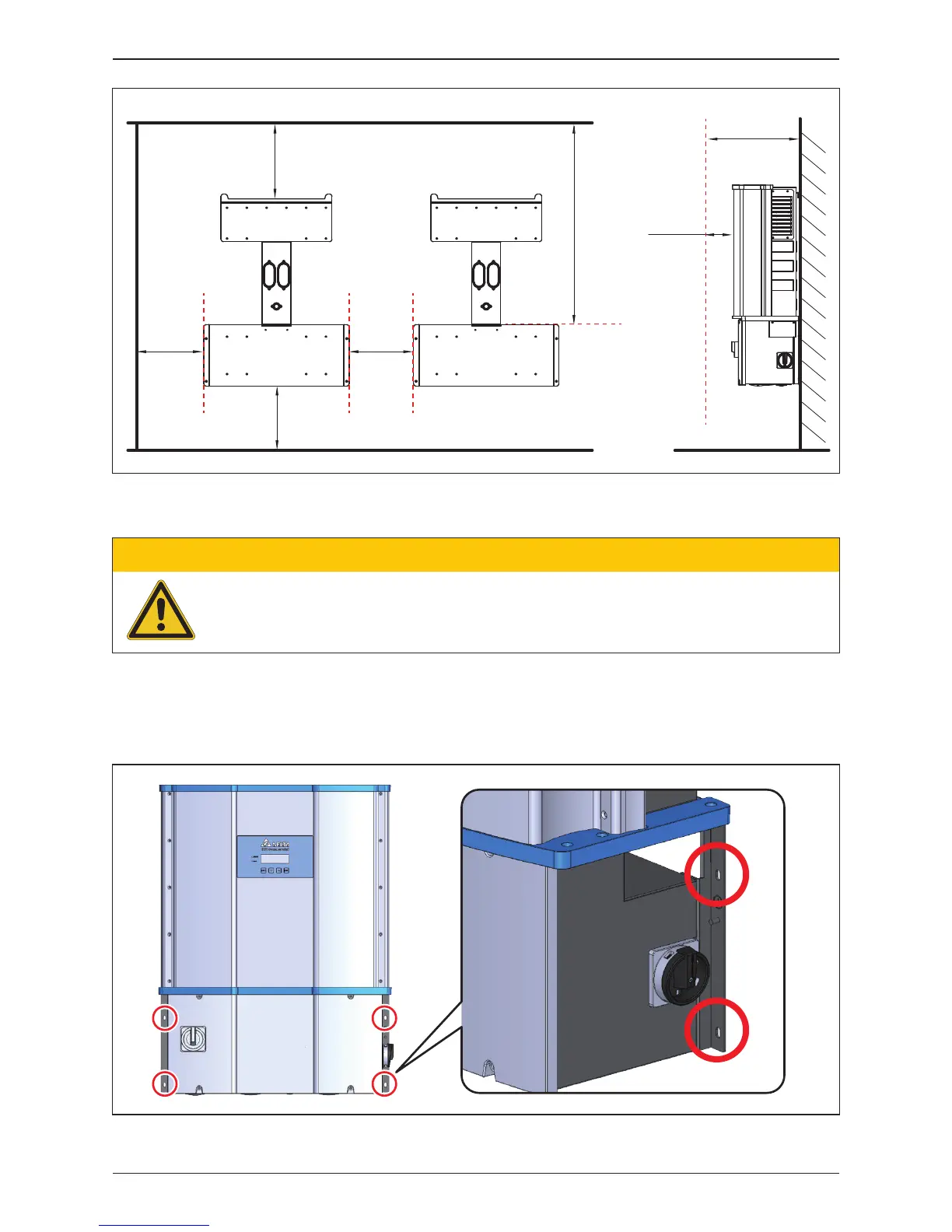
Figure 3-9: Screw locations to secure inverter WB to wall-mounting bracket
After installing the unit on the bracket, secure the wiring box to the bracket with
four screws per Figure 3-9. Tighten the screws to a torque of 40 lbf-in (4.5 N.m)
> 80cm
[31.5in]
> 80cm
[31.5in]
29
Installation