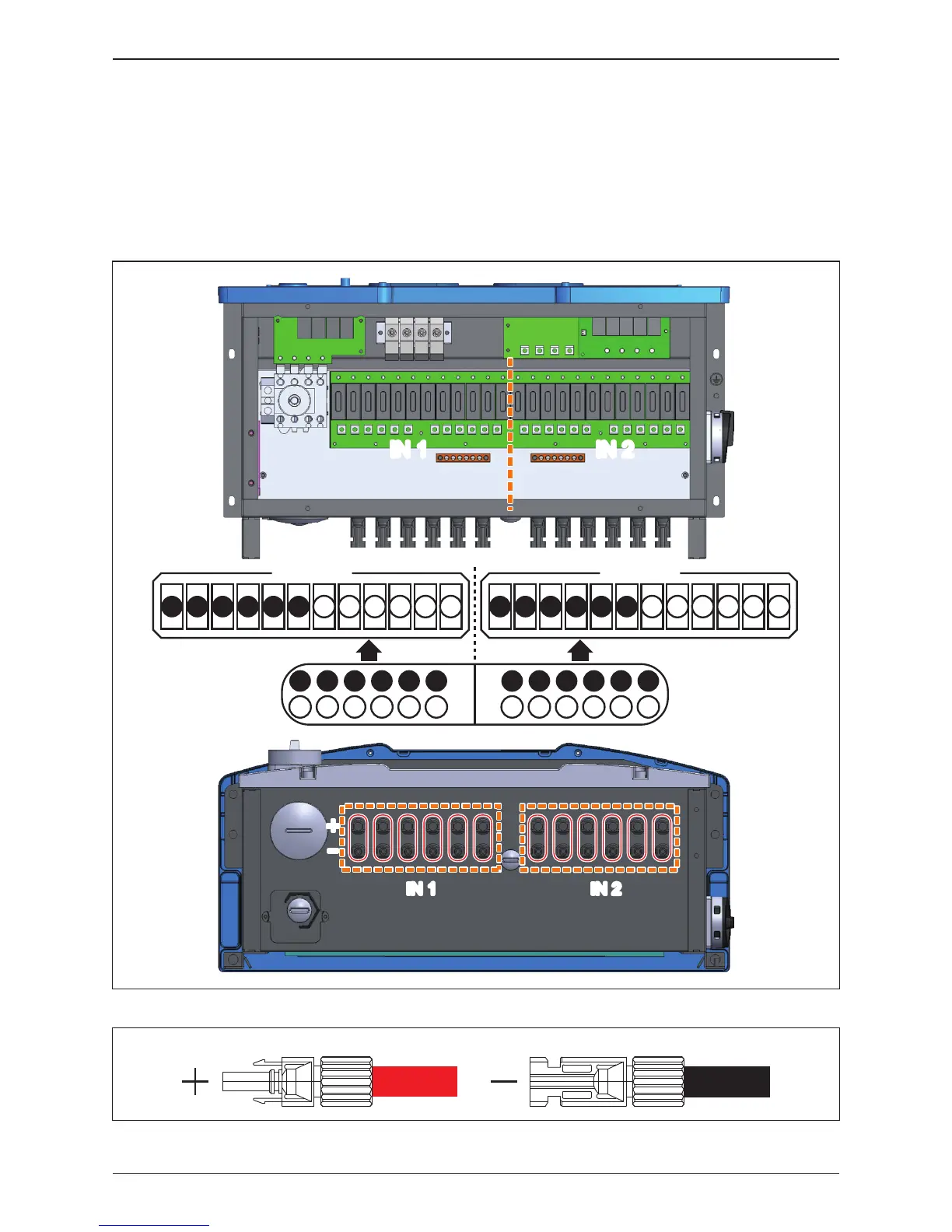
Figure 3-17: DC Wiring illustration
Please read the following instructions for connecting DC terminals (122 models):
• It is important to choose the proper size for DC cable.
• The cross-sectional area for each internal cable is 12~10 AWG (4~6mm²).
DC wiring polarities are divided into positive and negative, which is shown in
Figure 3-17. The connection shall be coherent with the indication marked on
inverter.
3.4.3 DC Wiring Installation for 122 models
Figure 3-16: Location for DC terminals for 122 models
+
-
IN 1 IN 2IN 1 IN 2
PV-KST 4/6 Ⅱ
PV-KBT 4/6 Ⅱ
+04 +05 +06+01 +02 +03 -01 -02 -03 -04 -05 -06
Fuse Board 1
+04 +05 +06+01 +02 +03 -01 -02 -03 -04 -05 -06
Fuse Board 2
+01
-01
+03
-
03
+05
-
05
+02
-
02
+04
-
04
+06
-
06
+01
-01
+03
-
03
+05
-
05
+02
-
02
+04
-
04
+06
-
06
IN 1
IN 2
IN 1 IN 2
41
Installation