Chapter 5 Parameters|VFD-B Series
5-46 Revision July 2008, BE16, SW V4.08 & V5.00
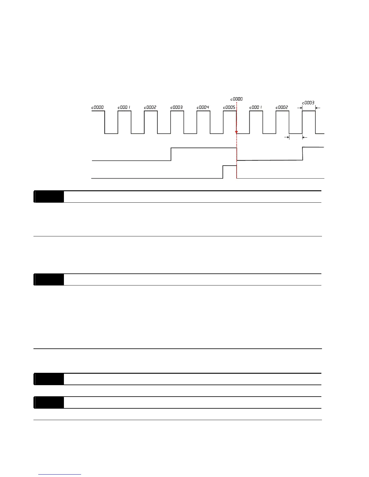
When the counter value reaches this value, the corresponding multi-function output terminal
will be activated, provided one of Pr.03-00 to Pr.03-03 set to 15 (Preliminary Count Value
Setting). This multi-function output terminal will be deactivated upon completion of Terminal
Count Value Attained.
The timing diagram:
Te r m i n al C o u nt Va l ue
(Pr. 03-00~Pr. 03-03=14)
Preliminary Count Value
(Pr. 03-00~Pr. 03-03=15)
Display
(Pr.00-04=01)
TRG
Counter Trigger
The width of trigger signal
should not be less than
2ms(<250 Hz)
2msec
2msec
Ex:03-08=5,03-09=3
03 - 11 EF Active when Preliminary Count Value Attained
Factory Setting: 00
Settings 00 Preliminary count value attained, no EF display
01 Preliminary count value attained, EF active
If this parameter is set to 01 and the desired value of counter is attained, the AC drive will treat
it as a fault. The drive will stop and show the “cEF” message on the display.
03 - 12 Fan Control
Factory Setting: 00
Settings 00 Fan always ON
01 1 minute after AC motor drive stops, fan will be OFF
02 AC motor drive runs and fan ON, AC motor drive stops and fan
OFF
03 Fan ON to run when preliminary heatsink temperature attained
This parameter determines the operation mode of cooling fan.
03 - 13 Brake Release Frequency Unit: 0.01
Settings 0.00 to 400.00Hz Factory Setting: 0.00
03 - 14 Brake Engage Frequency Unit: 0.01
Settings 0.00 to 400.00Hz Factory Setting: 0.00
These two parameters are used to set control of mechanical brake via the output terminals
(MO1~MO3) when Pr.03-00~03-03 is set to 29. Refer to the following example for details.