Chapter 5 Parameters|VFD-B Series
Revision July 2008, BE16, SW V4.08 & V5.00 5-87
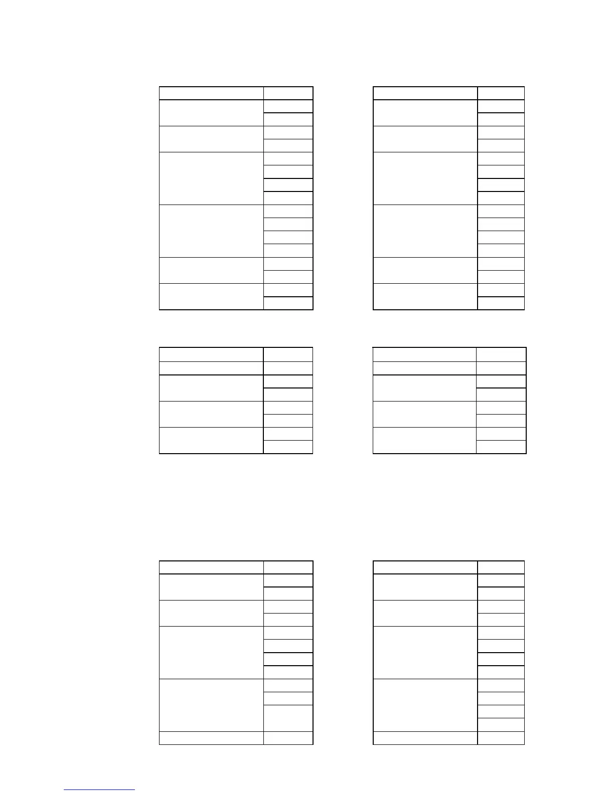
ASCII mode:
Command message: Response message:
STX ‘:’ STX ‘:’
‘0’ ‘0’
Address
‘1’
Address
‘1’
‘0’ ‘0’
Function
‘6’
Function
‘6’
‘0’ ‘0’
‘1’ ‘1’
‘0’ ‘0’
Data address
‘0’
Data address
‘0’
‘1’ ‘1’
‘7’ ‘7’
‘7’ ‘7’
Data content
‘0’
Data content
‘0’
‘7’ ‘7’
LRC Check
‘1’
LRC Check
‘1’
CR CR
END
LF
END
LF
RTU mode:
Command message:
Response message:
Address 01H Address 01H
Function 06H Function 06H
01H 01H
Data address
00H
Data address
00H
17H 17H
Data content
70H
Data content
70H
CRC CHK Low 86H CRC CHK Low 86H
CRC CHK High 22H CRC CHK High 22H
(3) 08H: loop detection
This command is used to detect if the communication between master device (PC or PLC) and AC
motor drive is normal. The AC motor drive will send the received message to the master device.
ASCII mode:
Command message: Response message:
STX ‘:’ STX ‘:’
‘0’ ‘0’
Address
‘1’
Address
‘1’
‘0’ ‘0’
Function
‘8’
Function
‘8’
‘0’ ‘0’
‘0’ ‘0’
‘0’ ‘0’
Data address
‘0’
Data address
‘0’
‘1’ ‘1’
‘7’ ‘7’
‘7’ ‘7’
Data content
‘0’
Data content
‘0’
LRC Check ‘7’ LRC Check ‘7’