Appendix B Accessories|VFD-B Series
B-26 Revision July 2008, BE16, SW V4.08 & V5.00
3. 7.5HP (5.5kW) and above
P
G
-
0
3
c
o
n
t
r
o
l
b
o
a
r
d
p
l
as
t
i
c
s t
a
nd
o
f
f
P
G
c
a
r
d
t
e
r
m
i
n
a
l
insulation
spacer
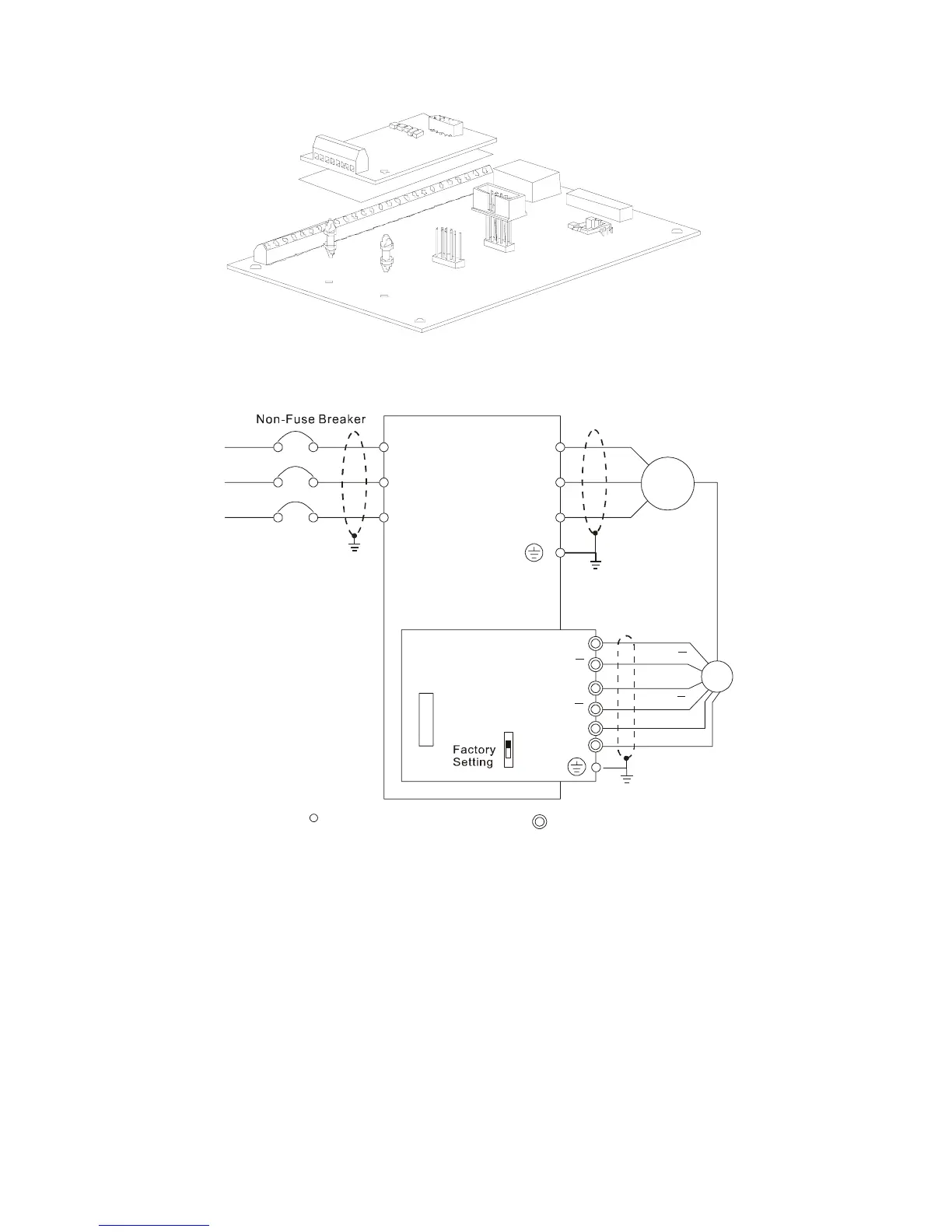
B.3.2.2 PG Card and Pulse Generator (Encoder)
1. Basic wiring diagram
NFB
R/L1
S/L2
T/L3
U/T1
V/T2
W/T3
M
3~
Motor
PG
A
B
12V
0V
PG-03
+12V
GND
OC
TP
Connection between PG-03 and the Encoder
*
Specification of the Encoder
is of the 12V/OC Output