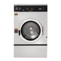
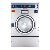
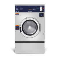
Machine Installation & Operation
Section 2: Installation & Operation
All washers must be installed in accordance with all local, state and national building, electrical,
and plumbing codes in effect in the area.
Foundation Requirements
The washer must be securely bolted to a substantial concrete fl oor, or mounted upon a suitable
base which is in turn securely bolted to a substantial concrete fl oor. Care must be stressed with
all foundation work to insure a stable unit, eliminating vibration. All installations must be made on
sound concrete fl oors 4” or thicker but see mounting dimensions for each model being installed.
Mounting
A concrete pedestal or steel mounting base which elevates the machine approximately 4 - 10
inches (101-250 mm) above the fl oor level is recommended to provide easy access to the load-
ing door. Allow a minimum of 24 inches (610mm) of clearance behind the rear of the machine, to
provide access for motor removal. If using Dexter bases, please make sure to use bevel washers
when mounting machine to base. Bevel washers can be purchased through the Dexter Parts
Department.
Proper Machine Grout Installation
Mix with water to a consistency that is easy to work with. Grout should be installed between base
(if used) and concrete fl oor on all side rails and crossmembers. If using a base you must grout
between base top and machine frame all side rails and crossmembers.
Mounting Holes
The following pages illustrate the mounting dimensions for the machine and also show a typical
base construction. Note: Mounting bolts should be checked frequently to insure that they remain
tight. The machine should be checked with a spinning load to be sure there is no unusual vibration
or movement between the machine and the base or fl oor.
Plumbing
Water supply hoses are furnished with each machine. The threaded connections on the hoses
are standard garden hose type thread. Separate hot and cold water lines with shut off valves
or faucets for inlet hose connections must be provided, maintaining 30 to 120 p.s.i. water fl ow
pressure. Maximum water temperature is 200 degrees.
Drain
The drain outlet tube at the rear of the machine is 3” in outside diameter on models T-400, T-
600, T-900, T-1200. A fl exible hose (# 9242-417-003) is available to extend the drain system for
these models. A drain outlet tube at the rear of the machine is 2 1/4” outside diameter on a T-300.
model. A fl exible hose ( #9242-417-001) is available to extend the drain system for these models.
16
 Loading...


