Amplifier board includes a 3-stage main amplifier channel, which gains to the input signal to
the 0...5 V range (this is the input range of the A/D converter, which is placed on the COMB
card). There is an offset potentiometer, P1 in the third amplifier stage, manufacturer sets the
correct offset voltage.
Adjust the offset voltage only in case it is out of the +/- 5mV range.
DHON signal (from the COMB card) switches on the LED in the HGB head via a transistor
(Q3), but the Photo Detector in the HGB head is working continuously.
The other side of the amplifier board contains special connectors for the chambers and the
HGB head.
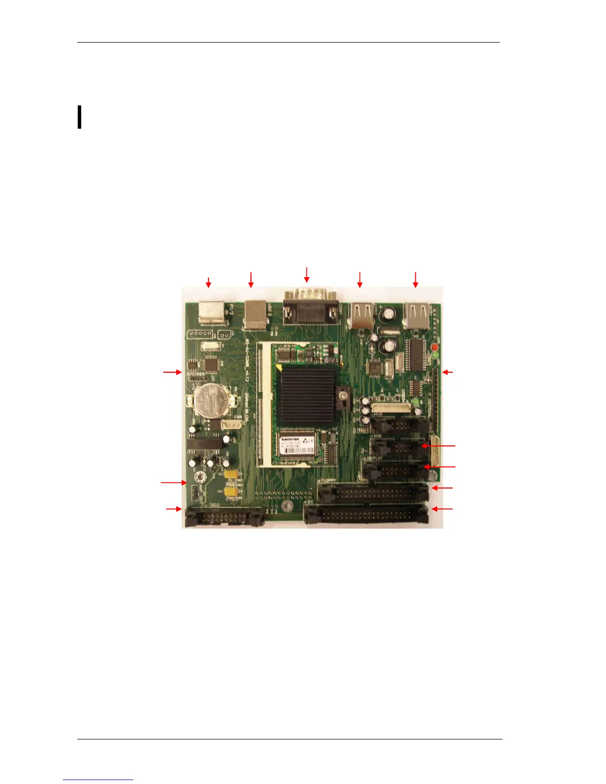
2.1.4. Control and Measurement Board (COMB) with DIMM-PC core
The compact COMB incorporates a single PC and its environmental functions, as well as the
specific measurement processing functions in one board.
PC system of the COMB board is based on the DIMM-PC module, which is a credit card
size PC with AMD Elan SC520 133 MHz micro-controller. DIMM-PC itself contains 16 or
32Mbyte RAM and same size of FlashDisk that acts like a hard disk. DIMM-PC module is
easily replaceable as it has an open socket (it has also a screw for safe fixing). COMB card
contains single ICs and some drivers/protection-circuits for the interfaces such as COM1,
PS2, USB, IDE and Speaker.
Measurement processing is based on a FPGA circuit. After power on, the FPGA holds the
DIMM-PC in wait state (with IOCHRDY signal) until the PIC configures the FPGA circuit from
the IDEPROM (status LED is red during configuration). After that the FPGA controls the
entire pneumatic system through the Pneumatic I
2
C bus, the Keyboard and Display module
with video RAM for MDA (Monochrome Display Adapter) emulation, and Start button &
status LED. FPGA circuit also performs measurement data acquisition by using the 10-bit
A/D chip. FPGA makes digital data processing and stores the results in the internal FIFO
memory. Cell parameters are sent to the DIMM-PC by single DMA cycles.