3. ADJUSTMENT
Mechanical and hardware adjustments are described in this section. Software settings are
included in Section 5.2.
3.1. Mechanical settings
There are two important mechanical settings in the system:
Opto wheel setting (Vertical motor)
Sampling needle setting
The manufacturer adjusts the analyzer during production. However, in case of
repairs in the mechanical system, these adjustments should be checked. The
omission of these settings can cause malfunction or damages to the instrument.
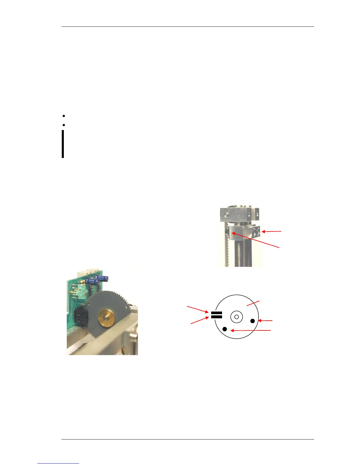
3.1.1. Opto wheel setting
This setting is necessary for the vertical motor movements because this adjustment sets the
opto end-switches of the H&V moving unit. The top of this block is called HV head and it is
shown in the figure below.
Set the distance to 1-2 mm between the moving
carriage and the stable part of the head.
belt.
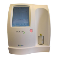
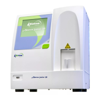
Adjust the opto wheel to home position, i.e. home hole
must be in home sensor, and LED corresponding to
home opto sensor goes on.
Check the end position as well: move the needle down. Adjustment is successful if end LED
goes on before moving part reaches end of mechanical range.
Once this adjustment is necessary, never miss sampling needle setting described in the next
section.