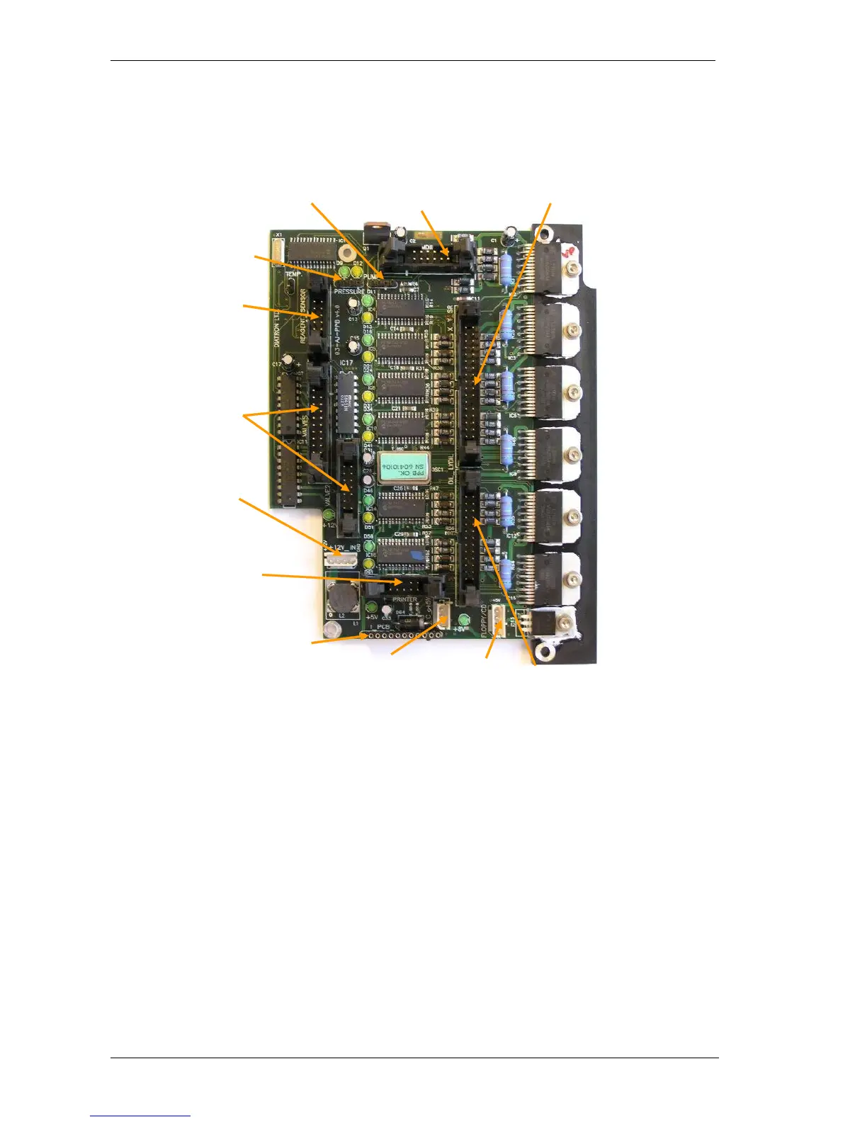
2.1.7. Pneumatic and Power Board (PPB)
PPB card contains the main power regulator circuits, valve and motor driver circuits and
PPB card contains the main power regulator circuits, valve and motor driver circuits and
other connections for the fluidic and p
Power system generates +5V (Digital power), +8V (Printer power) and +12V (Motor and
valve power) from the single +12V DC input signal.
Motor driver part consists of six separated PIC micro-controllers with power drivers.
Horizontal, Vertical and Sample rotor motors have one combined ribbon cable connection.
Main Dilutor (with two motors) and Micro-dilutor have separated connectors.
Valve driver section is based on the valve driver PIC micro-controller and three 8-bit,
powered output shift registers (with built in protection diodes) and there are two common
ribbon cable connections for the 4 valve boards. The peristaltic pump has a separated
Darlington driver circuit for more reliable operation.
All the 7 (6 for motors, 1 for pneumatic) microcontroller have 2 LEDs: a yellow one and a
green one.
The yellow one indicates motor moving or holding and active valve or pump moving. (it
means current flows into motors, valves or pump)