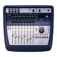
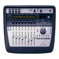
Chapter 4: Digi 002 Top Panel 35
Channel Record Ready Indicator
Each channel has a Record Ready LED. When a
track is record-enabled and the transport is
stopped, this LED flashes. When Pro Tools is re-
cording, it is lit continuously. (See “Record En-
able Switch” on page 35 for details on
record-enabling tracks.)
Rotary Encoders
These knobs control a variety of parameters, de-
pending on the view:
Home View The rotary encoders control pan po-
sition for each track, with the LED rings indicat-
ing the pan position with a single LED.
Console View The rotary encoders control send
levels for each track, with the LED rings indicat-
ing the send levels with an expanding series of
LEDs.
Channel View The rotary encoders control
plug-in, pan/send, or insert settings, depending
on the Channel View selection, with the LED
rings showing corresponding states.
Encoder/Meter LED Ring
Each rotary encoder has a circle of 15 LEDs
above it for indicating data values controlled by
the encoder. The style of display depends on the
type of data. For example, discrete or stepped in-
formation such as pan position or frequency
value is shown by a single LED, while an ex-
panding series of LEDs shows values such as
send levels, gain, or filter bandwidth.
The LED rings can also be set to show track lev-
els by pressing the Encoder/Meter Mode switch
to the right of the encoder area. When set to
Meter mode, the LED rings show increasing lev-
els in a clockwise manner, with the last red LED
indicating clipping.
Channel Scribble Strip
Each channel has a 4-character scribble strip
that displays a variety of information, including
track, send and insert names, pan position, send
levels, or plug-in control information. The de-
fault display is the name of the displayed ele-
ment. When you move a fader or rotary en-
coder, the scribble strip will temporarily display
the value for that control, then return to the de-
fault display.
Global Fader Controls
Immediately to the right of the channel faders,
there are global controls that affect the assign-
ment and operation of all the faders.
Record Enable Switch
Pressing the Record Enable switch followed by a
Channel Select switch arms the corresponding
track for recording.
To enable tracks for recording:
1 Press the Record Enable switch. When the
Record Enable function is active, the Record En-
able switch flashes.
2 Press the Channel Select switch for the tracks
you want to enable for recording. When a track
is armed for recording, its Record Ready indica-
tor flashes. During recording, its Record Ready
indicator is lit continuously.
3 To deactivate the Record Enable function,
press the Channel Select switch for the track,
then press the Record Enable switch a second
time.
To disable tracks for recording:
1 Press the Channel Select switch on any track
whose Record Ready indicator is flashing to dis-
arm the track for recording.