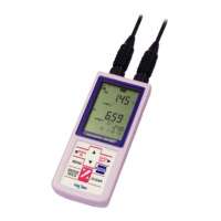
Model WQC-30 3. Name and Function of Each Part
-
20
-
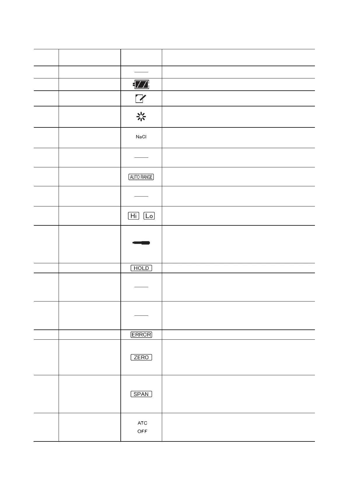
Name and function of each display section
Number Name
Notation
in the manual
Function
1 Data number display
• Displays the data number.
2 Battery symbol
• Displays the remaining battery level in 4 stages.
3 Memo symbol
• Indicates the display of memory data.
4 Operation indication
symbol
• Displays at startup
5 Salinity conversion
symbol
• Illuminates when displaying salinity.
6 Main display
• Displays measurement values. There are unit symbols above
and below the main display.
7 AUTO RANGE symbol
• Illuminates when performing auto-range (turbidity, electrical
conductivity).
8 Standard liquid bottle
symbol
• Illuminates when performing pH calibration.
9 Measurement range
symbol
• Illuminates the turbidity measurement range.
10 Sensor symbol
• Illuminates when the sensor module is connected.
• After calibration is started, it blinks during stabilit
determination and calibration execution, then illuminates full
upon completion of calibration.
11 Hold symbol • Illuminates when a measurement value is on hold.
12 Temperature display
• Displays the values of temperature measurements.
• After execution of temperature calibration, an underline is
displayed.
13 Date and time display
• Displays the current date and time and the date and
ime of the
saved data (Month/Day Hour: Minute).
• Displays the interval time.
14 Error symbol • Blinks when an error occurs.
15 Zero calibration symbol
• Illuminates after executing zero calibration (turbidity, dissolve
oxygen).
• Blinks when executing zero calibration (turbidity, dissolve
ox
en
.
16 Span calibration symbol
• Illuminates after executing cell constant calibration (electrical
conductivity).
• Blinks when executing span calibration (turbidity, dissolve
oxygen).
17 Temperature
compensation symbol
(ATC/OFF)
• Displays method of temperature compensation.
(“ATC”: automatic temperature compensation
“OFF”: no temperature compensation)
(Continues)
 Loading...