EasyManuals Logo

DMC SuperSigma2 User Manual

DMC SuperSigma2
97 pages
To Next Page IconTo Next Page
To Previous Page IconTo Previous Page
Page #24 background imageLoading...
Page #24 background image
SuperSigma2 AM PMS V1.5.6 17-1-2020 Page 24 (97) ©2019 DMC GmbH Herten Germany
Cal.
Ref.
Parameter
Calibrator
text
Min.
adjust
Max.
adjust
Step
size
Default
39
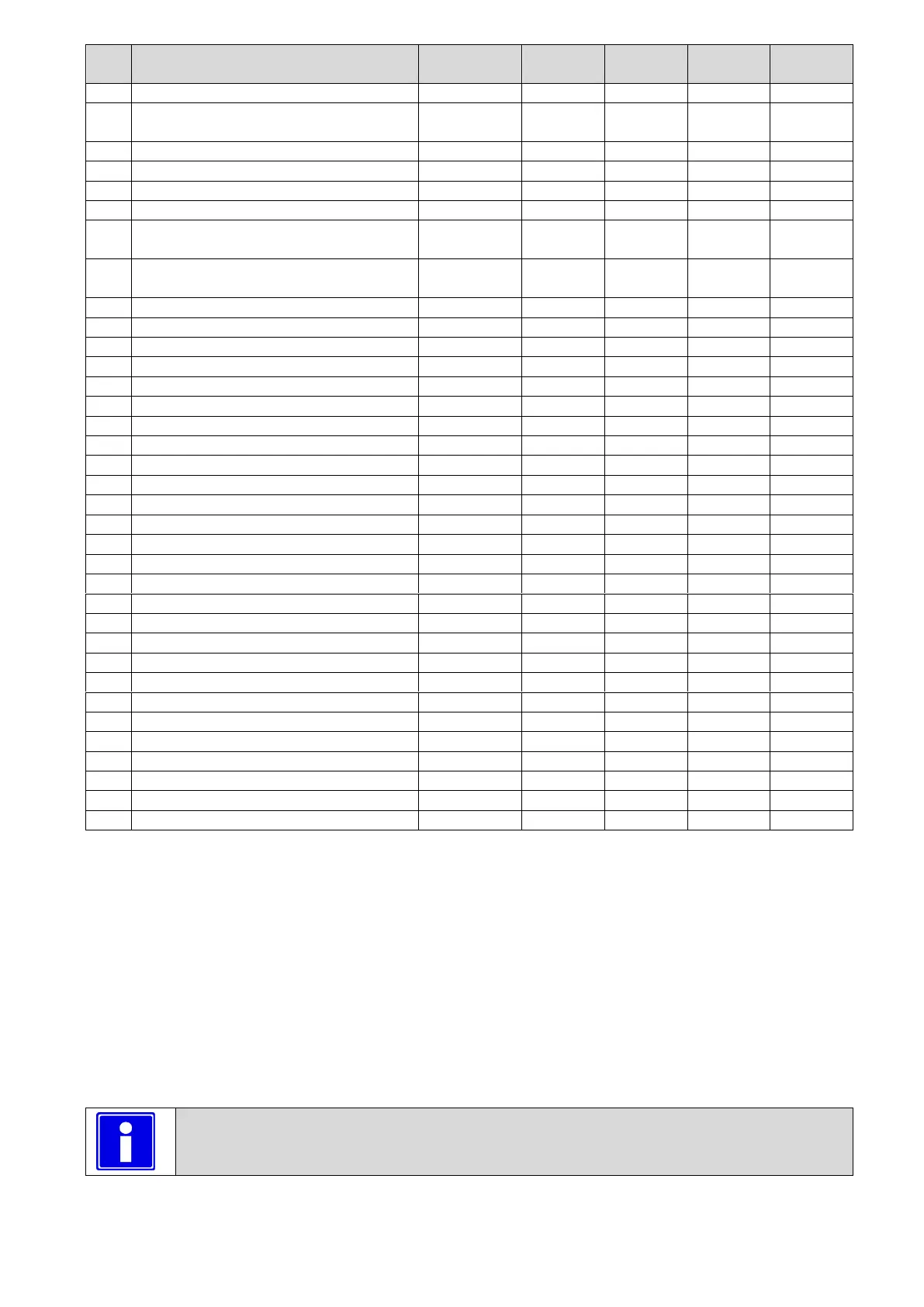
Neutral brake ramp time 2
NBrkRmp2
0.1 s
20.0 s
0.1 s
4.0 s
40
Direction Brake torque 2 (Torque Mode
Only)
DBrkTrq2
0 %
100 %
1 %
100 %
41
Direction brake ramp time 2
DBrkRmp2
0.1 s
20.0 s
0.1 s
4.0 s
42
Foot Brake Torque 2 (Torque Mode Only)
FBrkTrq2
0 %
100 %
1 %
50 %
43
Foot brake ramp time 2
FBrkRmp2
0.1 s
20.0 s
0.1 s
4.0 s
44
Cutback speed 3 (I/O 7 set to speed3)
Speed3
0.0 Hz
600.0 Hz
0.1 Hz
100.0 Hz
45
Handbrake On maximum Speed (I/O 7 set
to Handbrake)
HandBrk
0.0 Hz
400.0 Hz
0.1 Hz
10.0 Hz
46
Maximum Drive Torque speed 3 (I/O 7 set
to Handbrake)
MxDrTrq3
0 %
100 %
1 %
10 %
47
Speed limit ramp (torque control only)
SpLimRmp
0.1 s
20.0 s
0.1 s
10.0 s
48
Drive torque reduction time
DTrqRtm
0.1
3.0 s
0.1
0.8 s
49
Brake torque reduction time
BTrqRtm
0.1
3.0 s
0.1
0.8 s
50
Power steer delay
PStrDly
0.0 s
50.0 s
0.1 s
5.0 s
51
Electric brake delay
EBrkDly
0.1 s
50.0 s
0.1 s
0.5 s
52
Accelerator pot minimum
AccMin
0.0 V
10.0 V
0.1 V
0.2 V
53
Accelerator pot maximum
AccMax
0.0 V
10.0 V
0.1 V
4.6 V
54
Brake pot minimum
BrkMin
0.0 V
10.0 V
0.1 V
0.4 V
55
Brake pot maximum
BrkMax
0.0 V
10.0 V
0.1 V
4.6 V
56
Steer pot minimum
StrMin
0.00 V
10.00 V
0.01 V
0.20 V
57
Steer pot middle point
StrMid
0.00 V
10.00 V
0.01 V
2.50 V
58
Steer pot maximum
StrMax
0.00 V
10.00 V
0.01 V
4.80 V
59
Wig/Wag fwd threshold
FwdTH
0.0 V
10.0 V
0.1 V
3.0 V
60
Wig/Wag rev threshold
RevTH
0.0 V
10.0 V
0.1 V
2.0 V
61
Dual motor cut out
DMcut
1 %
100 %
1 %
10 %
62
Dual motor angle 1
DMang1
1 %
100 %
1 %
60 %
63
Dual motor angle 2
DMang2
1 %
100 %
1 %
70 %
64
Dual motor angle 3
DMang3
1 %
100 %
1 %
85 %
65
Dual motor speed 1
DMspd1
0 %
100 %
1 %
10 %
66
Dual motor speed 2
DMspd2
0 %
100 %
1 %
5 %
67
Dual motor speed 3
DMspd3
0 %
100 %
1 %
30 %
68
Speed ratio (display Kph)
SpdRatio
1.0
999.9
0.1
120.0
69
Vehicle max. speed
VmaxSpd
0.0 KPH
999.9 KPH
0.1 KPH
20.0 KPH
70
Safe stop Torque (Torque mode only)
SfStTorque
0 %
100 %
1 %
20 %
71
Safe stop Ramp Time
SfStRmpTm
0.1 s
10.0 s
0.1 s
1.0 s
72
Belly switch speed
BellySpd
0 Hz
600 Hz
0.1 Hz
50 Hz
73
Belly switch time
BellyTim
0 s
3 s
0.1 s
0.5 s
M1-1T Acceleration delay “Accel”
This sets the time taken to accelerate from zero torque demand to maximum torque demand in Torque Control mode, or
zero speed to maximum speed in Speed Control mode (according to “M3-2T Control Mode “Spd/Torq”” selection).
The maximum torque demand is set by M4-9 Maximum RMS motor current”, and it is assumed correspond to 100% of
deliverable Torque.
The maximum speed demand is set by M4-13 Maximum Motor Frequency”, and it is assumed correspond to 100% of
speed.
Increasing the value results in a slower vehicle acceleration, while decreasing the value results in a faster vehicle
acceleration.
If controller is in torque mode the acceleration delay correspond to the time, when accelerator fully pressed, for torque
to rise from 0 % to 100%.
If controller is in speed mode the acceleration delay correspond to the time, when accelerator fully pressed, for speed to
rise from 0 % to 100%.
Important for speed control:
When speed control selected (“M3-2T Control Mode “Spd/Torq””=0) using a very low value of time will
bring bumpy response to accelerator deflection.

Table of Contents

Questions and Answers:

Question and Answer IconNeed help?

Do you have a question about the DMC SuperSigma2 and is the answer not in the manual?

DMC SuperSigma2 Specifications

General IconGeneral
BrandDMC
ModelSuperSigma2
CategoryEngine
LanguageEnglish

Related product manuals