SuperSigma2 AM PMS – V1.5.6 17-1-2020 Page 86 (97) ©2019 DMC GmbH Herten Germany
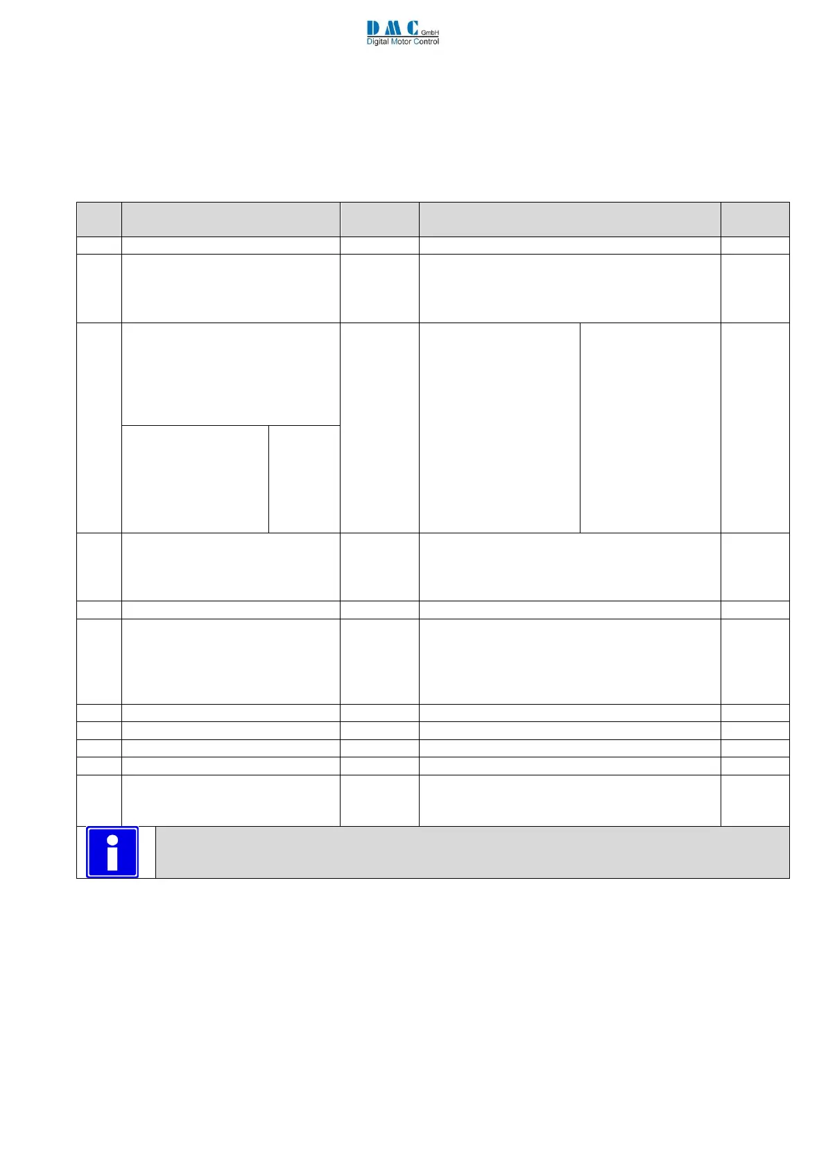
11 Menu 9 “CAN Bus Setup”
The SuperSigma2 controller uses our own CAN bus protocol for sending and receiving information to and from other CAN
nodes. The protocol is designed for the SuperSigma2 to act as a slave in an existing CAN environment. Detailed information
about the protocol will be provided on request. See [2] for further details.
As default the CAN system is deactivated.
Options (defaults are in bold)
CAN bus speed:
0 = 100kbps
1 = 125kbps
2 = 250kbps
Transmit/Receive CAN messages
Used short descriptions:
0= DC & DS
1 = DC & DS & MS
2 = DC & DS & CS
3 = DC & DS & CS & MS
4= no CAN message
5= DS only
6= MS only
7= DS & MS
8= CS only
9= CS & DS
10= CS & MS
11= CS & MS &DS
(Receive &Transmit)
(Receive &Transmit)
(Receive &Transmit)
(Receive &Transmit)
(Transmit only)
(Transmit only)
(Transmit only)
(Transmit only)
(Transmit only)
(Transmit only)
(Transmit only)
DC : drive command
DS : drive status
MS : Motor status
CS : controller status
(receive)
(transmit)
(transmit)
(transmit)
0 = No shared line contactor
1 = Shared line contactor
2 = Shared line contactor CAN HMI master
3 = Shared line contactor CAN HMI slave
Last Node Sharing Line Contactor
Can Control Type
(only Traction Software)
0 Speed Limit Via Can Disabled, Safe Stop 1
Disabled;
1 Speed Limit Via Can Enabled, Safe Stop Disabled;
2 Speed Limit Via Can Disabled, Safe Stop Enabled;
3 Speed Limit Via Can Enabled, Safe Stop Enabled;
CAN motor status transmit rate
CAN controller status transmit rate
CAN drive status transmit rate
CAN controller timeout timer
CAN node ID Via digital Inputs
0 standard node ID
1 Can node identification via DigInp 1,2,3 and 5
(active only if “CANMsgs” < 4)
Recycle the key switch to make changes active. (Also indicated on calibrator ‘key’)