EasyManuals Logo

DMC SuperSigma2 User Manual

DMC SuperSigma2
97 pages
To Next Page IconTo Next Page
To Previous Page IconTo Previous Page
Page #74 background imageLoading...
Page #74 background image
SuperSigma2 AM PMS V1.5.6 17-1-2020 Page 74 (97) ©2019 DMC GmbH Herten Germany
9 Menu 7 “Limits Setup”
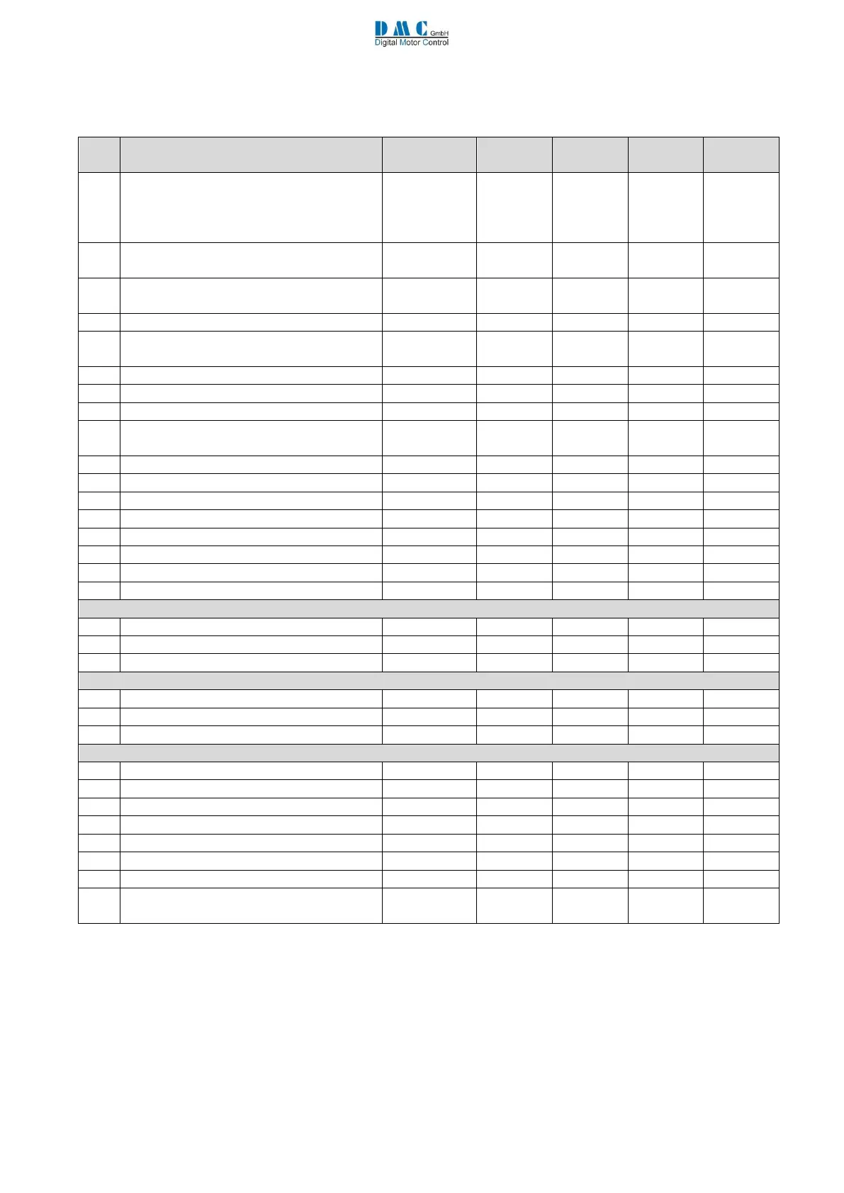
The following setup menu includes all the limits adopted for the controller safety.
Cal.
Ref.
Parameter
Calibrator
text
Min.
Max.
Step
size
Default
1
Motor Temp Sensor Type
(0 = KTY84-130
1 = Pt1000 1000 Ohm @0°c
2 = Pt1000 1000 Ohm @25°c )
MtempTyp
0
2
1
0
2
Motor Temp. Cutback start
TempStrt
0 °C
151 °C
(disables)
1 °C
140 °C
3
I²t Nominal Motor Current
NomCurr
(I2tInom
0 Arms
Unit max.
1 Arms
0 Arms
4
I²t Start Motor Temperature
I2tTemp
0 °C
100 °C
1 °C
0 °C
5
I²t Time
I2tTime
0 s
(disables)
2000 s
1 s
0 s
(disabled)
6
I²t Cutback1
I2tCutB1
0 %
100 %
1 %
100 %
7
I²t Cutback2
I2tCutB2
0 %
100 %
1 %
100 %
8
I²t Cutback3
I2tCutB3
0 %
100 %
1 %
100 %
9
Performance Table Speed 1
PTSpd1
0.0 %
(disables)
100.0 %
0.1 %
50.0 %
10
Performance Table Speed 2
PTSpd2
0.0 %
100.0 %
0.1 %
70.0 %
11
Performance Table Speed 3
PTSpd3
0.0 %
100.0 %
0.1 %
100.0 %
12
Performance Table Cutback 1
PTCutBk1
0 %
100 %
1 %
100 %
13
Performance Table Cutback 2
PTCutBk2
0 %
100 %
1 %
100 %
14
Performance Table Cutback 3
PTCutBk3
0 %
100 %
1 %
100 %
15
Low Voltage Cut Back start threshold
LVCBstrt
16.0 V
Unit max.
0.1 V
20.0 V
16
Low voltage cut back end threshold
LVCBend
16.0 V
Unit max.
0.1 V
16.0 V
17
Low voltage error threshold
LVerror
14.0 V
Unit max.
0.1 V
14.0 V
48 V units
18
High Voltage Cut Back start threshold
HVCBstrt
24.0 V
67.5 V
0.1 V
60.0 V
19
High voltage cut back end threshold
HVCBend
24.0 V
67.5 V
0.1 V
67.5 V
20
High voltage error threshold
HVerror
24.0 V
70.0 V
0.1 V
70.0 V
96 V units
18
High Voltage Cut Back start threshold
HVCBstrt
24.0 V
138.5 V
0.1 V
130.0 V
19
High voltage cut back end threshold
HVCBend
24.0 V
138.5 V
0.1 V
138.5 V
20
High voltage error threshold
HVerror
24.0 V
140.0 V
0.1 V
140.0 V
Generic
21
Absolute maximum motor speed
AbsMaxSp
0.0 Hz
700.0 Hz
0.1 Hz
200.0 Hz
22
Torque Threshold for Stall Protection
TrqTHLim
1.0%
100.0%
0.1%
100.0%
23
Stall protection Time
StallTim
0.0 sec
120.0 sec
0.1 sec
60.0 sec
24
n/a
25
n/a
26
Timed Current Limit Threshold Timer
IthTime
0 sec
60 sec
1 sec
0 sec
27
Timed Current Limit Current Threshold
CurrTh
10 A
Unit max.
1A
Unit max.
28
Timed Current Limit Lower Maximum
Current
ImaxLow
10 A
Unit max.
1A
Unit max.
M7-1 Motor Temp Sensor Type MtempTyp”
This parameter select the type of motor temperature sensor connected to pins 34 and 35 of the 35 Way connector:
if set to 0 a KTY84-130 sensor has to be connected;
if set to 1 a Pt1000 sensor that has 1000 Ohm @0°C has to be connected;
if set to 2 a Pt1000 sensor that has 1000 Ohm @25°C has to be connected.
Refer to Pin 34 Thermistor AD4 i/p and Pin 35 Thermistor 0V for details of connection.

Table of Contents

Questions and Answers:

Question and Answer IconNeed help?

Do you have a question about the DMC SuperSigma2 and is the answer not in the manual?

DMC SuperSigma2 Specifications

General IconGeneral
BrandDMC
ModelSuperSigma2
CategoryEngine
LanguageEnglish

Related product manuals