F6300 Power System Simulator User Guide
72A-2337-01 Rev. B 11/05 5-11
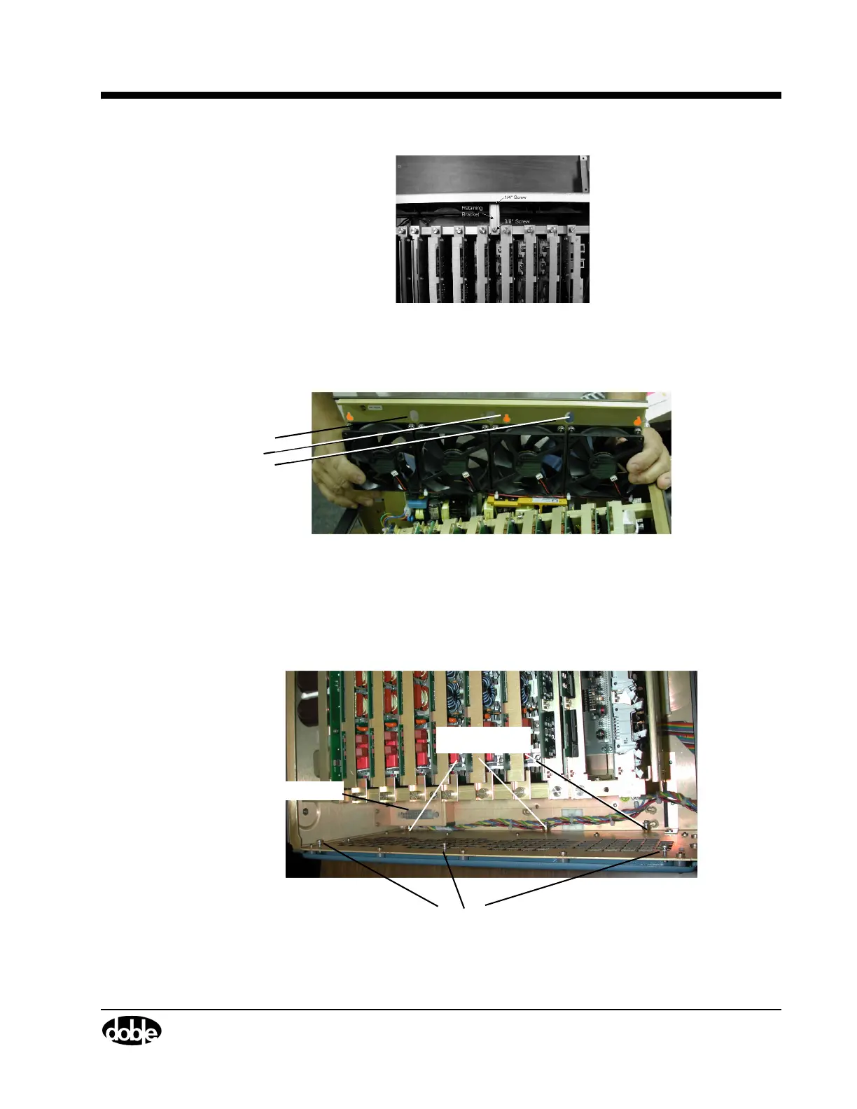
Figure 5.11 Retaining Bracket for Cooling Fan Assembly
5. Loosen the Phillips head screws that secure each end of the assembly. These screws fit inside
oblong shaped holes on the assembly rail (
Figure 5.12).
Oblong
Screw
Holes
Figure 5.12 Screw Holes on Fan Assembly Rail
6. Slide the board upward; tilt it forward; pull the board up and out of the chassis.
7. Ensure that you do not snag or nick any wires on the assembly.
Study the instrument chassis with the Fan Assembly removed (Figure 5.13). Prior to replacing this
style fan assembly, locate the electrical connector, the various standoffs, and screws.
.
Mounting Screws (3)
Electrical Connector
Standoffs (3)
Figure 5.13 Instrument Chassis with Fan Assembly Removed