(4) Adjust caster using measurements viewed on
DRBIII screen, and camber using measurements
viewed on wheel alignment equipment. (Refer to 2 -
SUSPENSION/WHEEL ALIGNMENT - SPECIFICA-
TIONS)
(5) When adjustments are complete, remove
Adapters/Inclinometers.
FRONT AND REAR TOE
Static toe position should be the final adjustment
made to the vehicle during the alignment procedure.
Adjusting rear toe first is recommended.
NOTE: It is recommended to leave the engine run-
ning during the front wheel toe setting procedure to
ease centering of the wheel.
(1) Start engine and turn wheels in both directions
before straightening and centering steering wheel.
Center steering wheel and retain with steering wheel
clamp. Leave engine running.
REAR TOE
NOTE: Repeat the following procedure at each rear
corner of the vehicle as necessary.
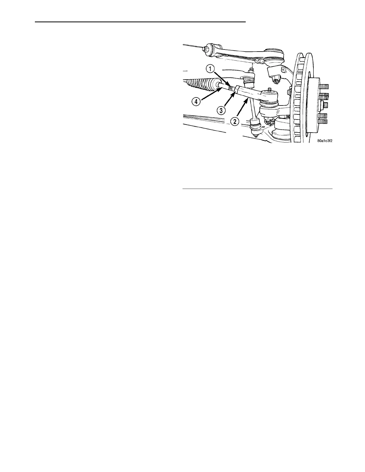
(1) Loosen tie rod jam nut (Fig. 22).
(2) Grasp toe link at adjustment serration (Fig.
22). Rotate toe link in direction required to obtain
specified individual wheel toe position. (Refer to 2 -
SUSPENSION/WHEEL ALIGNMENT - SPECIFICA-
TIONS)
(3) Tighten and torque tie rod jam nut to 75 N·m
(55 ft. lbs.).
FRONT TOE
NOTE: Repeat the following procedure at each front
corner of the vehicle as necessary.
(1) Remove clamp from end of steering gear boot
where it contacts inner tie rod.
(2) Loosen tie rod jam nut (Fig. 22).
(3) Grasp inner tie rod at adjustment serration
(Fig. 22). Rotate inner tie rod in direction required to
obtain specified individual wheel toe position. (Refer
to 2 - SUSPENSION/WHEEL ALIGNMENT - SPEC-
IFICATIONS)
(4) Tighten and torque tie rod jam nut (Fig. 22) to
75 N·m (55 ft. lbs.).
(5) Remove any twist in steering gear inner tie rod
boot caused by rotating inner tie rod. Install clamp
where previously removed.
(2) Remove steering wheel clamp.
(3) Remove all alignment equipment from vehicle.
(4) Remove Caster Angle Adapters/Inclinometers
from front or rear knuckles.
(5) Install belly pan. (Refer to 23 - BODY/EXTERI-
OR/BELLY PAN - INSTALLATION)
(6) Remove ballast weight from vehicle allowing
vehicle to return to curb height.
ADJUSTMENTS - DYNAMIC TOE PATTERN
This vehicle’s suspension system is designed to
vary the wheel toe pattern according to the vehicle
ride posture to keep the wheels pointed in the proper
direction at all times. The four wheel independent
suspension alignment must be correct to assure
proper road handling. The frame and suspension
components are calibrated at the assembly plant and
should not require adjustment unless the vehicle has
collision damage. This section will cover procedures
for correcting improper frame, steering gear, and rear
toe link alignment that would affect the wheel toe
pattern.
Wheel toe pattern is regulated by the vertical posi-
tioning of the inner tie rod pivot in relation to the
orbital swing of the wheel spindle (Fig. 23). Wheel
toe settings have no effect on toe pattern. When the
suspension is fully compressed and then extended
with the tie rod disconnected from the spindle, the
spindle makes an arc in space without altering the
toe pattern. When the arc of the spindle is extended
into a full circle and the inner tie rod end is posi-
tioned in the center of the circle, the toe pattern can-
not change. When the inner tie rod is raised or
lowered from the center of the true circle of the spin-
dle arc, the toe pattern will vary. When the suspen-
sion is compressed (jounce), the wheel toe should
change from normal riding height. When the suspen-
Fig. 22 Static Wheel Toe Position Adjustment
(Typical)
1 - ADJUSTMENT SERRATION
2 - OUTER TIE ROD
3 - JAM NUT
4 - INNER TIE ROD
ZB WHEEL ALIGNMENT 2 - 71
WHEEL ALIGNMENT (Continued)
 Loading...


