CONDITION POSSIBLE CAUSE CORRECTION
PROPELLER SHAFT VIBRATION 1. Undercoating or other foreign
material on shaft.
1. Clean exterior of shaft and wash
with solvent
2. Loose U-joint clamp screws. 2. Tighten screws properly.
3. Loose or bent U-joint yoke or
excessive runout.
3. Install replacement yoke.
4. Incorrect drive line angularity. 4. Correct angularity
5. Rear spring center bolt not in
seat.
5. Loosen spring U-bolts and seat
center bolts.
6. Worn U-joint bearings. 6. Install replacement propeller
shaft.
7. Propeller shaft damaged (bent
tube) or out of balance.
7. Install replacement propeller
shaft.
8. Broken rear spring. 8. Replace rear spring.
9. Excessive runout or unbalanced
condition.
9. Reindex propeller shaft 180
degrees, test and correct as neces-
sary.
10. Excessive drive pinion gear
shaft yoke runout.
10. Reindex propeller shaft 180
degrees and evaluate.
UNIVERSAL JOINT NOISE 1. U-joint clamp screws loose. 1. Tighten screws with specified
torque.
2. Lack of lubrication. 2. Replace U-joint.
PROPELLER SHAFT BALANCE
If propeller shaft balance is suspected, it can be
verified with the following procedure.
NOTE: Removing and re-indexing the propeller
shaft 180° may eliminate some vibrations.
Clean all the foreign material from the propeller
shaft and the universal joints (mud, undercoating,
etc.).
Inspect the propeller shaft for missing balance
weights, broken welds, and bent areas. If the pro-
peller shaft is found with any of these condi-
tions, the shaft must be replaced.
Ensure the universal joints are not worn, are prop-
erly installed, and correctly aligned with the shaft.
Check the universal joint clamp screws torque.
Check universal joint angles.
(1) Raise and support the vehicle.
(2) Remove the wheels/tires. Install the wheel lug
nuts to retain the brake discs.
(3) Mark and number the propeller shaft tube
approximately six inches from the yoke weld end at
four positions 90° apart.
(4) Run and accelerate the vehicle until vibration
occurs. Note the intensity and speed the vibration
occurred. Stop the engine.
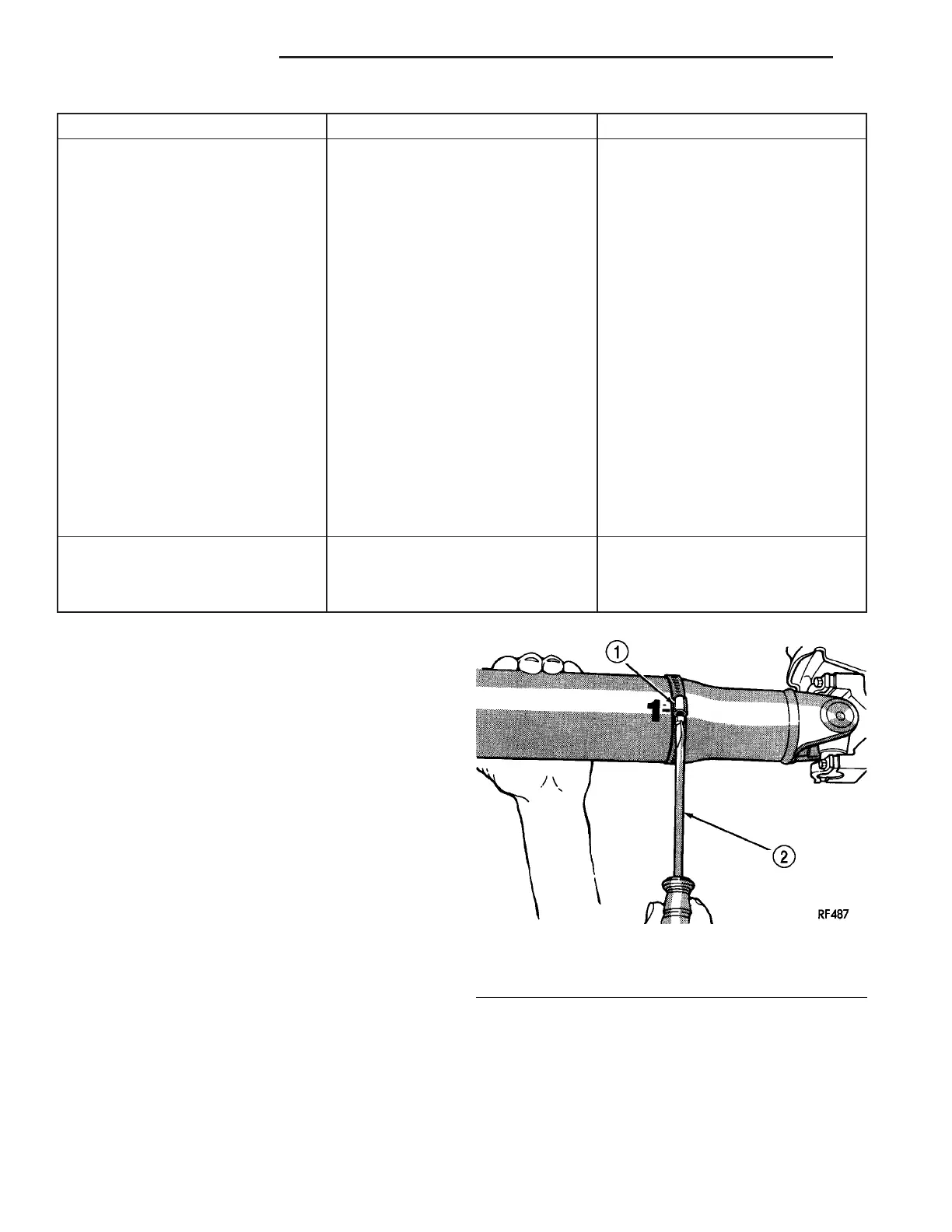
(5) Install a screw clamp at position 1 (Fig. 1).
(6) Start the engine and recheck for vibration. If
there is little or no change in vibration, move the
clamp to one of the other three positions. Repeat the
vibration test.
(7) If there is no change in amount of vibration at
other positions, the vibration may not be caused by
prop shaft unbalance.
Fig. 1 CLAMP AT POSITION 1
1 - CLAMP
2 - SCREWDRIVER
3 - 2 PROPELLER SHAFT ZB
PROPELLER SHAFT (Continued)















 To Next Page