BRAKE PADS/SHOES -
FRONT/REAR
STANDARD PROCEDURE - BRAKE SHOE
BURNISHING
When new brake shoe and lining assemblies are
installed on the vehicle, this procedure must be used
to correctly burnish (seat) the brake lining to the
brake rotor discs.
(1) Accelerate the vehicle to a steady speed of 40
mph.
(2) Using light brake pedal pressure, slow the
vehicle from 40 mph to 0 mph in approximately 6
seconds.
(3) Accelerate back up to 40 mph for approxi-
mately 1 minute to allow the brakes to cool down.
(4) Repeat this procedure 15 to 20 times to cor-
rectly seat the brake lining material.
REMOVAL
NOTE: Review all Warnings and Cautions. (Refer to
5 - BRAKES - WARNING)
(1) Raise vehicle. (Refer to LUBRICATION &
MAINTENANCE/HOISTING - STANDARD PROCE-
DURE).
NOTE: Perform steps Step 2 through Step 8 on
each side of vehicle to complete shoe set removal.
(2) Remove wheel and tire assembly. (Refer to 22 -
TIRES/WHEELS - REMOVAL)
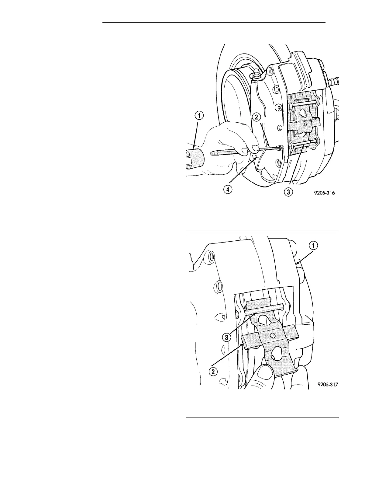
(3) Using pin punch and hammer on outboard end,
tap lower brake shoe support pin out of caliper (Fig.
7).
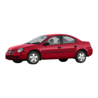
(4) Remove brake shoe spring clip out from under
the upper support pin still in caliper (Fig. 8).
(5) Using pin punch and hammer, remove upper
brake shoe support pin in same fashion used on
lower support pin (Fig. 9).
CAUTION: When pushing pistons back into caliper
bores, use only a trim stick as shown (Fig. 10) or
other suitable soft tool. Never use a screwdriver or
other metal pry bar due to potential damage to
braking surface of rotor.
(6) Before new brake shoes can be installed in cal-
iper, caliper pistons must be pushed back into bores
of caliper. To do this correctly without damaging the
caliper, pistons, dust boots or braking disc, perform
the following:
(a) Place trim stick between inboard brake shoe
and outer edge of the rotor (Fig. 10).
(b) Using trim stick, apply pressure against the
inboard brake shoe until both pistons are com-
pletely bottomed in bores of inboard caliper half.
Leave trim stick in place to hold pistons in place.
Fig. 7 Removing Lower Support Pin
1 - HAMMER
2 - PUNCH
3 - SUPPORT PIN
4 - OUTBOARD SIDE OF CALIPER ASSEMBLY
Fig. 8 Spring Clip
1 - CALIPER ASSEMBLY
2 - SPRING CLIP
3 - UPPER BRAKE SHOE SUPPORT PIN
5 - 12 BRAKES - BASE ZB





 To Next Page