INSTALLATION
NOTE: Perform steps Step 1 through Step 8 on
each side of vehicle to complete shoe set removal
before proceeding with step Step 9.
(1) If NEW brake shoes are being installed in cal-
iper, caliper pistons must be seated in bores of cali-
per. If they are not, refer to procedure outlined in
REMOVAL to do so. (Refer to 5 - BRAKES/HYDRAU-
LIC/MECHANICAL/BRAKE PADS/SHOES -
REMOVAL)
(2) Install NEW inboard and outboard brake shoes
into opening in disc brake caliper (Fig. 11). Make
sure beveled end of each shoe lining is directed
against the direction the rotor is rotating in
when vehicle is moving forward. Front shoes
need to have beveled end facing downward;
rear shoes need to have beveled end facing
upward.
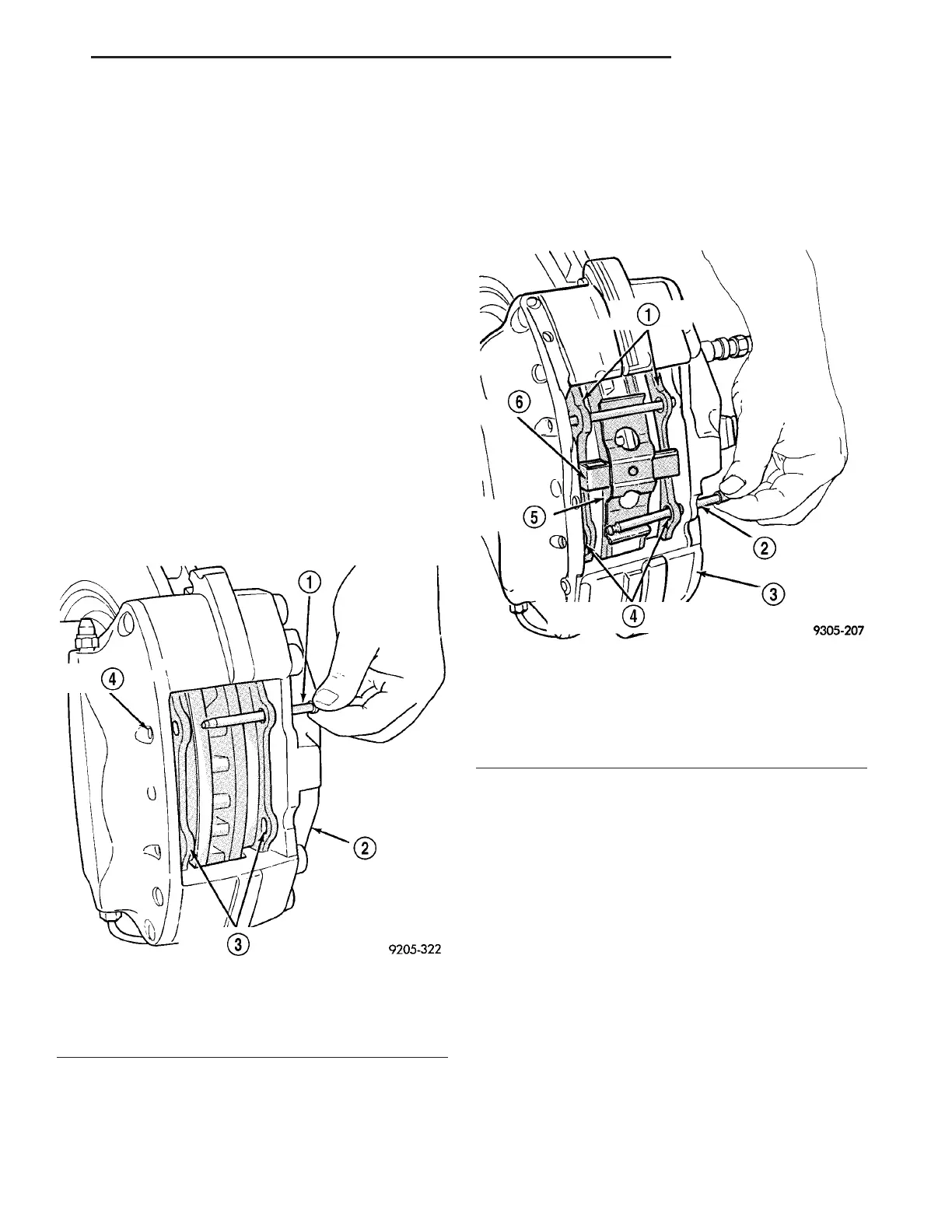
(3) From inboard side, install upper brake shoe
support pin through caliper and upper holes in both
brake shoes (Fig. 14). Ensure that small end of sup-
port pin is in hole in outboard caliper half.
(4) Install brake shoe spring clip under upper
brake shoe assembly support pin (Fig. 8).
(5) Press down on lower end of spring clip until it
touches brake rotor. Then install lower brake shoe
support pin through caliper and lower holes in both
brake shoes in the same fashion the upper pin was
installed (Fig. 15). Ensure spring clip is beneath
lower support pin and small end of the support pin is
in hole in outboard caliper half.
(6) From inboard side, seat upper and lower sup-
port pins into caliper using a pin punch and a ham-
mer (Fig. 16). Support pins must be driven into
caliper until support pin retaining rings are locked
into place.
(7) Once support pins are fully installed into cali-
per, inspect assembled caliper to make sure spring
clip is centered in opening of caliper and is resting
against both brake shoes (Fig. 17).
(8) Install wheel and tire assembly (Refer to 22 -
TIRES/WHEELS - INSTALLATION). Progressively
tighten wheel mounting (lug) nuts in proper sequence
to 122 N·m (90 ft. lbs.) torque.
(9) Lower vehicle.
(10) Pump brake pedal several times to ensure
vehicle has firm brake pedal to adequately stop vehi-
cle.
(11) Check and adjust brake fluid level as neces-
sary.
Fig. 14 Installing Brake Shoe Upper Support Pin
1 - SUPPORT PIN
2 - DISC BRAKE CALIPER ASSEMBLY
3 - BRAKE SHOE ASSEMBLY SUPPORT PIN HOLES
4 - SUPPORT PIN HOLE
Fig. 15 Installing Brake Shoe Lower Support Pin
1 - BRAKE SHOE ASSEMBLIES
2 - LOWER SUPPORT PIN
3 - DISC BRAKE CALIPER ASSEMBLY
4 - BRAKE SHOE ASSEMBLY SUPPORT PIN HOLES
5 - BRAKING DISC
6 - SPRING CLIP
ZB BRAKES - BASE 5 - 15
BRAKE PADS/SHOES - FRONT/REAR (Continued)





 To Next Page